
The Anatomy of an Electronics Component Manufacturer
When you unseal an anti-static bag containing an STM32 microcontroller, a Texas Instruments TLV1117 voltage regulator, or a Murata multilayer ceramic capacitor (MLCC), you are holding the end result of a multi-billion-dollar global supply chain. Understanding how an electronics component manufacturer transforms raw materials into functional logic, memory, and power devices is critical for hardware engineers and PCB designers. In 2026, as advanced 2.5D/3D packaging and wide-bandgap semiconductors like Silicon Carbide (SiC) and Gallium Nitride (GaN) dominate high-power and RF markets, the traditional boundaries between fabrication and assembly have blurred.
This technical explainer deconstructs the exact lifecycle of component manufacturing, tracing the journey from front-end wafer fabrication to back-end assembly, automated testing, and final distribution. According to the Semiconductor Industry Association (SIA), the manufacturing process requires hundreds of precise steps, taking up to four months from raw silicon to a finished, packaged chip.
Business Models: IDM vs. Fabless vs. OSAT
Before diving into the cleanroom, it is essential to understand the structural models that govern modern component production. Not every brand on your PCB actually owns the factory that made the silicon.
| Model | Definition | Examples (2026) | CapEx Requirement | Primary Focus |
|---|---|---|---|---|
| IDM | Integrated Device Manufacturer. Owns both design and fabrication facilities (fabs). | Texas Instruments, STMicroelectronics, Intel, Vishay | Extremely High ($10B - $20B+ per new fab) | Analog, Power, Discrete, Legacy Nodes |
| Fabless | Designs the IC architecture but outsources physical manufacturing to foundries. | Qualcomm, NVIDIA, AMD, Espressif | Moderate (R&D and IP licensing focus) | Digital Logic, AI Accelerators, SoCs |
| Foundry | Pure-play fabrication facilities that manufacture wafers for Fabless companies. | TSMC, GlobalFoundries, Samsung Foundry | Extremely High (EUV lithography tooling) | Advanced Nodes (3nm, 5nm, 7nm) |
| OSAT | Outsourced Semiconductor Assembly and Test. Handles dicing, packaging, and testing. | ASE, Amkor, JCET | Low to Moderate | Packaging, Wire Bonding, Final Test |
Phase 1: Front-End Wafer Fabrication (The Cleanroom)
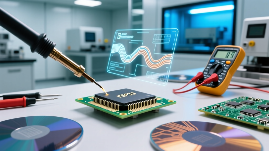
The front-end process occurs in a Class 1 or Class 10 cleanroom, where airborne particles are virtually eliminated. The foundation of most ICs is a 300mm (12-inch) silicon wafer, grown via the Czochralski process into a massive single-crystal ingot and sliced into discs less than 1mm thick.
Photolithography and Nanoscale Patterning
Photolithography is the heartbeat of the fab. A photosensitive chemical (photoresist) is spun onto the wafer. For advanced nodes (7nm and below), an electronics component manufacturer relies on Extreme Ultraviolet (EUV) lithography scanners, such as the ASML NXE:3600B, which costs upwards of $150 million per unit. EUV light (13.5nm wavelength) projects circuit patterns through a reticle onto the wafer. The NIST Nanoscale Device Characterization Division continuously researches metrology at these atomic scales to ensure yield viability.
Etching, Doping, and Deposition
- Etching: Plasma etchers (using gases like CF4 or Cl2) carve away exposed material to create nanoscale trenches and vias.
- Ion Implantation: Dopants (Boron for P-type, Phosphorus/Arsenic for N-type) are accelerated into the silicon lattice at high voltages to alter electrical conductivity, forming the source, drain, and channel regions of MOSFETs.
- Deposition: Chemical Vapor Deposition (CVD) and Physical Vapor Deposition (PVD) lay down insulating dielectrics (like silicon dioxide) and conductive metal layers (copper or tungsten).
A single microcontroller may undergo 40 to 60 of these iterative mask-and-etch layers before the wafer is complete.
Phase 2: Back-End Assembly and Packaging
Once fabrication is complete, the 300mm wafer is sent to an OSAT (or an IDM's internal back-end facility) for packaging. This phase transforms fragile silicon dies into robust components capable of surviving automated PCB assembly.
Dicing and Die Attach
The wafer is mounted on a UV-sensitive dicing tape. Modern manufacturers use stealth laser dicing rather than mechanical diamond saws, as lasers eliminate kerf loss (material wasted by the saw blade) and prevent micro-cracking in brittle materials like SiC. Individual dies are then picked and placed onto a leadframe or substrate using a silver-filled epoxy or eutectic solder.
Interconnects: Wire Bonding vs. Flip-Chip
Electrical connections between the silicon die and the external package pins are established via two primary methods:
- Wire Bonding: Used for legacy, analog, and low-cost microcontrollers. A capillary tool bonds ultra-fine gold or copper wires (typically 15 to 50 micrometers in diameter) from the die's bond pads to the leadframe.
- Flip-Chip (C4 Process): Used for high-pin-count BGA packages (like FPGAs and AI accelerators). Solder bumps are deposited directly on the die pads, the die is flipped upside down, and reflowed onto the substrate. This drastically reduces parasitic inductance and allows for thousands of I/O connections.
Engineering Callout: Moisture Sensitivity Levels (MSL)
The epoxy molding compounds (EMC) used to encapsulate ICs are hygroscopic. If moisture penetrates the package and the component is subjected to 260°C reflow temperatures, the water vaporizes, causing the 'popcorn effect' (internal delamination or cracking). Manufacturers bake and seal components in dry-packs with desiccant based on JEDEC J-STD-020 MSL ratings. If you are prototyping and leave an MSL-3 component exposed to ambient lab humidity for over 168 hours, you must rebake it at 125°C for 24 hours before SMD reflow soldering.
Phase 3: Automated Test Equipment (ATE) and Binning
An electronics component manufacturer cannot ship untested silicon. Final testing ensures that the component meets the datasheet specifications for voltage, current, timing, and thermal limits. This is handled by massive Automated Test Equipment (ATE) systems, such as the Teradyne UltraFLEX or Advantest V93000, which cost between $2M and $10M per installation.
Speed Binning and the Bathtub Curve
Due to microscopic variations in the fab process, not all chips on a wafer perform identically. ATE systems perform speed binning. A batch of identical ARM Cortex-M4 dies might be tested at 168MHz. Those that pass are binned and sold as '168MHz' parts. Those that fail are retested at 120MHz; if they pass, they are sold as lower-tier, cheaper SKUs.
To eliminate 'infant mortality' failures, manufacturers subject a sample of components to Burn-In Testing. According to standards tracked by the JEDEC Solid State Technology Association, burn-in typically involves powering the IC at its maximum rated voltage while baking it in an oven at 125°C for 168 hours. This forces early-life defects to manifest in the factory rather than in the field, adhering to the reliability 'bathtub curve'.
Phase 4: Sourcing Realities for Prototyping Engineers in 2026
Understanding the manufacturer's process directly impacts how you source components for prototyping and low-volume production. The global supply chain has shifted heavily toward localized inventory and strict traceability.
Decoding Date Codes and Traceability
Every component leaving a manufacturer features a laser-etched or ink-stamped Date Code (e.g., '2542' meaning the 42nd week of 2025). When sourcing from authorized distributors like Mouser, Digi-Key, or Arrow, you are guaranteed lot traceability back to the specific wafer lot and ATE test batch.
The Counterfeit Threat in Legacy Nodes
Because building a new fab for legacy nodes (e.g., 130nm to 350nm used in basic op-amps and power management ICs) is economically unviable, older components are prime targets for counterfeiters. Fraudsters will sand down the markings of cheap, out-of-spec chips and reprint the logos of premium electronics component manufacturers. Actionable Defense: Always inspect the blacktopping (the matte epoxy surface) under a 10x loupe. Authentic manufacturer laser etching reveals a slight texture variation and sharp, high-contrast edges, whereas counterfeiters often use a uniform black paint overcoat that chips at the edges and smells of acetone when swabbed with isopropyl alcohol.
Summary for Circuit Designers
The journey from a silicon ingot to a taped-and-reeled SMD component involves immense capital expenditure, atomic-level precision, and rigorous statistical testing. By understanding the distinction between IDMs and Fabless models, the physical constraints of packaging interconnects, and the critical importance of MSL handling and ATE binning, hardware engineers can make more informed component selections, design more reliable PCBs, and navigate the complex 2026 electronics supply chain with confidence.