
The Evolution of the Switch Electronic Component
When designing power stages and control circuits in 2026, selecting the correct switch electronic component is one of the most critical decisions an engineer or hobbyist will make. The days of relying solely on mechanical toggles are long gone. Today, power switching requires balancing switching speed, thermal management, galvanic isolation, and cost. Whether you are driving a 12V DC motor with PWM or switching a 240V AC heating element, the physics of your chosen switch will dictate your circuit's efficiency and lifespan.
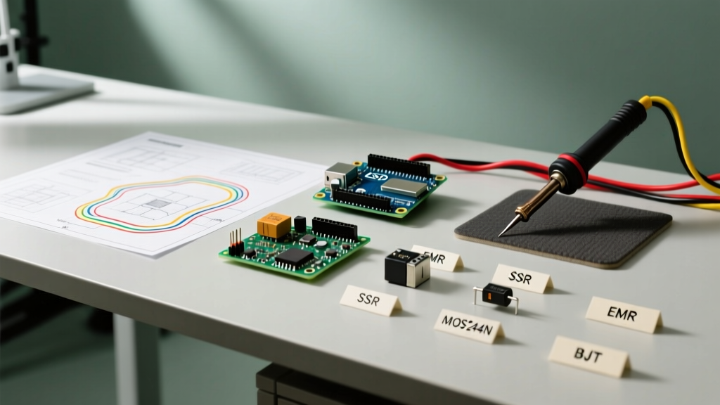
In this comprehensive comparison, we dissect the four primary contenders for power switching: Electromechanical Relays (EMRs), Solid-State Relays (SSRs), Power MOSFETs, and Bipolar Junction Transistors (BJTs). We will analyze specific 2026 market pricing, real-world failure modes, and exact part numbers to help you make an informed design choice.
1. Electromechanical Relays (EMR): The Galvanic Workhorse
The electromechanical relay remains a staple in industrial and automotive applications. An EMR uses a magnetic coil to physically pull metal contacts together, closing the circuit.
Component Spotlight: Omron G5LE-14-DC12
- Type: SPDT PCB Power Relay
- Max Continuous Current: 10A at 250VAC / 125VDC
- Coil Power: 400mW
- Typical Cost (2026): $0.85 - $1.10 per unit
Pros and Ideal Use Cases
EMRs provide true galvanic isolation between the low-voltage control circuit and the high-voltage load. They also boast an exceptionally low on-resistance (typically under 50 milliohms), meaning they generate virtually no heat when conducting current. According to Omron's technical guide on relays, modern AgSnO2 (Silver Tin Oxide) contact materials have vastly improved resistance to contact welding under high inrush currents.
Failure Modes and Edge Cases
The primary drawback of the EMR is mechanical wear. A standard relay is rated for 100,000 electrical operations. If you attempt to use an EMR for PWM (Pulse Width Modulation) at 1kHz, the contacts will physically destroy themselves in less than two seconds. Additionally, contact bounce (typically 1-5ms upon closure) can cause voltage spikes in inductive loads, necessitating snubber circuits or flyback diodes.
2. Solid-State Relays (SSR): The Silent AC Switch
Solid-state relays replace moving parts with semiconductor switches—usually TRIACs for AC loads or MOSFET arrays for DC loads—paired with an optocoupler for isolation.
Component Spotlight: Crydom D2425
- Type: Panel Mount AC SSR (Zero-Cross)
- Max Continuous Current: 25A at 280VAC
- Control Voltage: 3-32VDC
- Typical Cost (2026): $22.00 - $26.00 per unit
Pros and Ideal Use Cases
SSRs offer infinite mechanical life (rated for >100 million operations) and completely silent operation. The Crydom D2425 features zero-cross switching, meaning it waits for the AC sine wave to cross 0V before turning on. This drastically reduces inrush currents and electromagnetic interference (EMI) when switching resistive AC loads like heaters or incandescent bulbs. For deeper semiconductor theory, All About Circuits' semiconductor textbook provides excellent foundational knowledge on how these internal opto-isolated TRIACs function.
Failure Modes and Edge Cases
Unlike EMRs, SSRs have a significant voltage drop across the internal semiconductor (typically 1.2V to 1.6V). At 25A, a 1.5V drop equates to 37.5W of heat dissipation. Thermal runaway is the most common SSR failure mode; if you do not mount a 25A SSR to a properly sized heatsink with thermal paste, it will overheat and fail short-circuit. Furthermore, SSRs exhibit off-state leakage current (usually 1-5mA), which can cause sensitive loads to glow faintly or behave erratically when the switch is supposedly 'off'.
3. Power MOSFETs: The High-Speed DC King
For DC switching, especially where high-frequency PWM is required, the Power MOSFET (Metal-Oxide-Semiconductor Field-Effect Transistor) is the undisputed champion.
Component Spotlight: Infineon IRLB8721 (Logic Level)
- Type: N-Channel Power MOSFET
- Max Continuous Drain Current (Id): 62A (at 25°C case temp)
- Rds(on): 2.7mΩ at Vgs = 4.5V
- Typical Cost (2026): $1.10 - $1.45 per unit
Pros and Ideal Use Cases
The IRLB8721 is a 'logic-level' MOSFET, meaning it fully turns on with a 4.5V or 5V gate signal directly from a microcontroller like an Arduino or ESP32, without needing a dedicated gate driver. With an Rds(on) of just 2.7 milliohms, pushing 10A through this device generates only 0.27W of heat (P = I²R), often eliminating the need for a heatsink entirely. MOSFETs can switch in nanoseconds, making them perfect for motor speed control, LED dimming, and switch-mode power supplies.
Failure Modes and Edge Cases
MOSFETs lack inherent galvanic isolation; a fault on the high-voltage side can easily travel back through the gate and fry your microcontroller. The most common failure mode is gate oxide puncture caused by electrostatic discharge (ESD) or voltage spikes exceeding the maximum Vgs rating (usually ±20V). Additionally, driving MOSFETs with high gate charge (Qg) directly from a microcontroller GPIO pin can cause slow switching transitions, leading to massive heat generation in the linear region. Always use a dedicated gate driver (like the TC4420) for high-frequency, high-Qg applications.
4. Bipolar Junction Transistors (BJTs): The Legacy Budget Option
While largely superseded by MOSFETs in modern power design, BJTs—specifically Darlington pairs—still appear in legacy designs and ultra-low-budget educational kits.
Component Spotlight: STMicroelectronics TIP120
- Type: NPN Darlington Transistor
- Max Continuous Collector Current (Ic): 5A
- Vce(sat): ~2.0V at 3A
- Typical Cost (2026): $0.35 - $0.50 per unit
Pros and Ideal Use Cases
The TIP120 is incredibly cheap and requires very little base current to drive large loads due to its high internal DC current gain (hFE > 1000). It is perfectly adequate for switching small 12V relays, low-power solenoids, or simple indicator lights where efficiency is not a priority.
Failure Modes and Edge Cases
The Darlington configuration's fatal flaw is its high collector-emitter saturation voltage (Vce(sat)). Unlike a MOSFET's resistive drop, a BJT acts like a diode when saturated. A 2V drop at 3A means the TIP120 is dissipating 6W of heat. Without a massive heatsink, the TIP120 will trigger its internal thermal shutdown or suffer secondary breakdown. Furthermore, BJTs are current-controlled devices, meaning they continuously draw base current while on, wasting power compared to the voltage-controlled, near-zero static gate current of a MOSFET.
Comparative Analysis Matrix
To synthesize the data, refer to the comparison matrix below. This framework should be your first stop when evaluating a switch electronic component for a new PCB layout or breadboard prototype.
| Parameter | EMR (Omron G5LE) | SSR (Crydom D2425) | MOSFET (IRLB8721) | BJT (TIP120) |
|---|---|---|---|---|
| Load Type | AC or DC | AC (Zero-Cross) | DC Only | DC Only |
| Switching Speed | Slow (5-10ms) | Medium (8.3ms / half-cycle) | Ultra-Fast (<100ns) | Fast (<1µs) |
| PWM Capable? | No | No (Phase angle control only) | Yes (Up to MHz range) | Yes (Up to ~20kHz) |
| Galvanic Isolation | Yes (Magnetic) | Yes (Optical) | No | No |
| On-State Loss | Negligible (<50mΩ) | High (1.2V - 1.6V drop) | Very Low (2.7mΩ) | High (~2.0V drop) |
| 2026 Unit Cost | ~$0.95 | ~$24.00 | ~$1.25 | ~$0.40 |
The 2026 Decision Framework: Which Switch Should You Choose?
Use this step-by-step logic flow to finalize your component selection:
- Is the load AC Mains (120V/240V)?
- If you need to switch it on/off cleanly with isolation: Choose an SSR.
- If you are on a strict sub-$2 budget and switching infrequently: Choose an EMR.
- Is the load DC, and do you need PWM (motor speed, LED dimming)?
- Choose a Logic-Level Power MOSFET. Ensure your microcontroller's GPIO voltage exceeds the MOSFET's Vgs(th) threshold.
- Is the load DC, but you absolutely require galvanic isolation to protect a sensitive sensor network?
- Use an EMR, or combine an optocoupler with a MOSFET.
- Are you switching a simple low-power DC load (<1A) and optimizing purely for BOM cost?
- A BJT like the 2N2222 or a small signal MOSFET like the 2N7000 will suffice. Avoid Darlingtons like the TIP120 unless you specifically need high gain for a weak signal source.
Expert Prototyping Tip: When testing high-current MOSFETs on a solderless breadboard, remember that standard breadboard clips are rated for a maximum of 1A to 2A. Pushing 10A through breadboard jumper wires will melt the plastic housing and cause a fire hazard. Always solder high-current switch electronic components directly to a perfboard or custom PCB with adequate copper pour for thermal relief.
Final Thoughts on Component Longevity
The landscape of power electronics continues to shift toward wide-bandgap semiconductors like Silicon Carbide (SiC) and Gallium Nitride (GaN). While these are currently overkill for standard 12V/24V DIY and prototyping projects, they are rapidly becoming the standard in commercial EV and solar inverters. For the vast majority of makers and electrical engineers building in 2026, mastering the interplay between EMRs for isolated AC switching and Logic-Level MOSFETs for high-efficiency DC control will cover 95% of your design requirements. Always consult the manufacturer's datasheet for exact thermal derating curves before finalizing your PCB layout.