
The Hidden Physics of Component Degradation
When engineers and hobbyists think about electronic component storage, they usually picture plastic bins and labeled drawers for physical organization. However, from a materials science perspective, proper storage is an active defense mechanism against chemical and electrochemical degradation. Modern integrated circuits (ICs), surface-mount devices (SMDs), and precision passives are highly reactive micro-structures. If left exposed to ambient environments, they succumb to three primary failure modes: moisture-induced delamination, electrostatic discharge (ESD), and lead oxidation.
Understanding how professional electronic component storage works requires looking at the physics of the materials involved. This guide breaks down the exact mechanisms of degradation and the engineered solutions used to halt them.
Mechanism 1: Moisture Ingress and the 'Popcorn Effect'
The most catastrophic failure mode in surface-mount technology (SMT) is the "popcorn effect." The epoxy molding compound (EMC) that encapsulates ICs is slightly hygroscopic, meaning it naturally absorbs water vapor from the ambient air over time.
The Physics of Delamination: When a moisture-saturated IC passes through a reflow soldering oven, the internal temperature rapidly spikes to 260°C (500°F). At this temperature, the trapped moisture instantly vaporizes into steam. Because steam occupies approximately 1,600 times the volume of liquid water, the resulting internal vapor pressure exceeds the tensile strength of the EMC. The package literally cracks open from the inside, destroying the silicon die and the wire bonds.
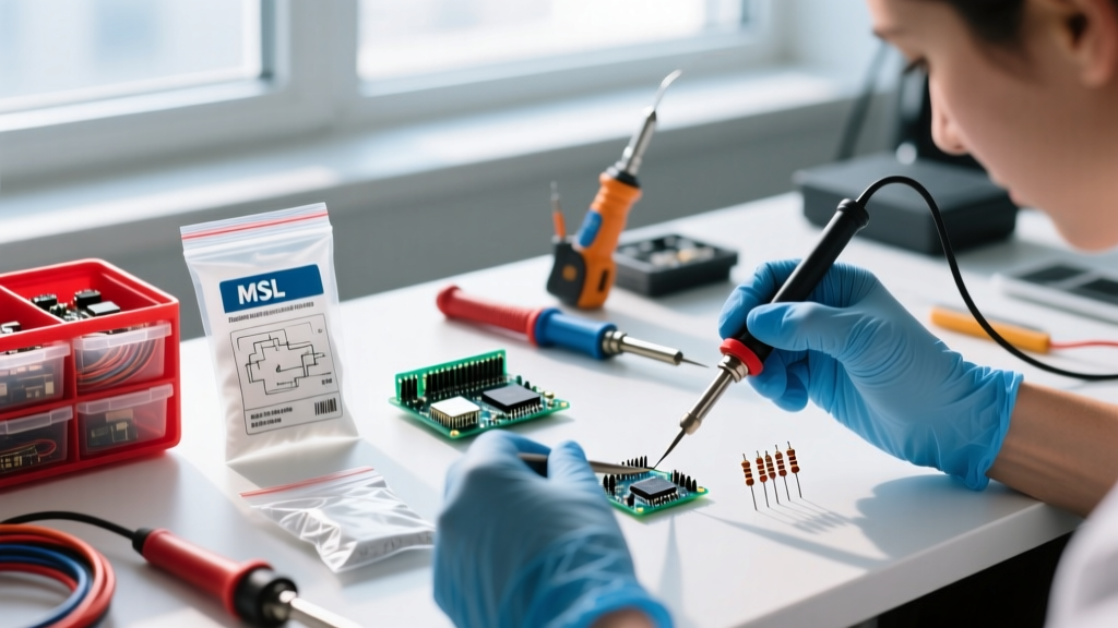
To combat this, the industry relies on the IPC/JEDEC J-STD-033 standard, which categorizes components by their Moisture Sensitivity Level (MSL). Proper electronic component storage for MSL-rated parts requires vacuum-sealing them with desiccants and Humidity Indicator Cards (HICs).
MSL Ratings and Floor Life Limits
| MSL Rating | Max Floor Life (at <30°C / 60% RH) | Storage Requirement |
|---|---|---|
| 1 | Unlimited | Standard ambient storage |
| 2 | 1 Year | Dry cabinet or sealed bag |
| 3 | 168 Hours (7 Days) | Strict dry cabinet (<10% RH) |
| 4 | 72 Hours (3 Days) | Strict dry cabinet (<10% RH) |
| 5 | 48 Hours (2 Days) | Strict dry cabinet (<5% RH) |
| 6 | Must bake before use | Immediate bake & reflow |
Note: Data derived from JEDEC solid state technology standards. If a component exceeds its floor life, it must be "baked" in a specialized convection oven at 40°C to 125°C for 8 to 48 hours to drive the moisture out before soldering.
Mechanism 2: Electrostatic Discharge (ESD) Shielding
While a 2mm static spark is barely visible to the human eye, it can carry thousands of volts. Modern CMOS transistors feature gate oxides that are only a few nanometers thick; a discharge of just 50 volts can punch a microscopic hole through the gate, causing immediate death or latent failure (where the part passes initial testing but degrades rapidly in the field).
According to guidelines published by the ESD Association, storing sensitive components requires a Faraday cage effect. This is where the distinction between "anti-static" and "static-shielding" bags becomes critical.
Anatomy of a Static-Shielding Bag
True static-shielding bags (typically silver/gray) are multi-layered laminates engineered to route electrostatic charges around the bag, not through it. A standard 3M StatShield bag features four distinct layers:
- Outer Layer (Polyester/PET): Provides mechanical puncture resistance and is treated with a topical anti-static agent to prevent triboelectric charging (charge generation via friction).
- Second Layer (Aluminum Sputtering): A microscopic layer of vapor-deposited aluminum that acts as the Faraday cage, reflecting and routing ESD strikes around the exterior.
- Third Layer (Polyester): Adds structural integrity and separates the metal layer from the interior.
- Inner Layer (LLDPE): Linear low-density polyethylene that is inherently anti-static, ensuring the components inside do not generate charge when rubbing against the bag.
Warning: Pink polyethylene bags are only "anti-static." They prevent the bag itself from generating a charge, but they offer zero shielding against external ESD strikes. Never store bare ICs in pink bags without an outer Faraday cage.
Mechanism 3: Oxidation and Solderability Failure
The third enemy of electronic component storage is atmospheric oxidation and sulfurization. Component leads are typically plated with finishes like SAC305 (Tin/Silver/Copper) or pure matte tin to ensure proper wetting during soldering.
When exposed to high humidity and airborne sulfur (common in industrial areas or near cardboard packaging), the tin reacts to form tin sulfide or tin oxide. This tarnish layer acts as a thermal and chemical barrier. When the part hits the solder wave or reflow oven, the flux cannot penetrate the thick oxidation layer, resulting in "non-wetting" or "de-wetting" defects. The solder balls up and rolls off the lead, causing an open circuit.
The Role of Desiccants in Halting Oxidation
To prevent oxidation, the relative humidity (RH) inside the storage environment must be kept below 5%. This is achieved using specialized desiccants. For electronic component storage, Montmorillonite clay desiccant (meeting MIL-D-3464 Type I standards) is vastly superior to standard silica gel.
- Silica Gel: Absorbs moisture well at room temperature, but if the ambient temperature inside a sealed bag rises (e.g., sitting in a warm warehouse), silica gel can actually release its trapped moisture back into the air.
- Montmorillonite Clay: Maintains its moisture-holding capacity across a much wider temperature gradient, ensuring the internal RH remains stable even if the storage facility experiences thermal cycling.
Architecting a Professional Storage Environment
For high-volume prototyping labs or production facilities in 2026, relying solely on vacuum-sealed bags is inefficient because breaking the seal resets the component's floor life. The industry standard solution is the electronic dry cabinet.
How Dry Cabinets Work
Unlike simple airtight boxes with desiccant packets, modern dry cabinets (such as the Eureka MSD1401-B, which retails for approximately $1,450) use active dehumidification. They employ a Zeolite desiccant wheel system. A slow-moving rotor coated in Zeolite absorbs moisture from the cabinet's internal air. A small heating element then bakes the moisture out of the Zeolite on the opposite side of the wheel, venting it outside the cabinet. This allows the cabinet to maintain a precise 2% to 5% RH indefinitely without ever needing to replace desiccant packets.
Storage System Checklist for MSL 3+ Components
- Primary Enclosure: Active Zeolite dry cabinet set to <5% RH.
- Monitoring: Calibrated digital hygrometer with a ±2% accuracy margin (NIST-traceable).
- Backup (for transit): 3.5-mil thick metal-in static shielding bags, heat-sealed (not zip-tied or folded).
- Indicators: 3-spot Humidity Indicator Cards (5%, 10%, 15%) placed inside sealed backup bags.
- Desiccant: MIL-D-3464 Type I clay desiccant packs, calculated at 1 unit per 0.03 cubic meters of bag volume.
Summary: Storage as an Active Engineering Process
Effective electronic component storage is not a passive administrative task; it is an active engineering process designed to manipulate thermodynamics, electrostatics, and chemistry. By understanding the physics of the popcorn effect, the Faraday cage mechanics of shielding bags, and the chemical realities of lead oxidation, you can eliminate latent micro-failures before they ever reach the PCB. Whether you are storing a $2 microcontroller or a $500 FPGA, treating storage as a critical phase of the manufacturing lifecycle ensures your designs perform exactly as simulated.