
Decoding the 40-Pin Header: Physical RPi GPIO Pinout
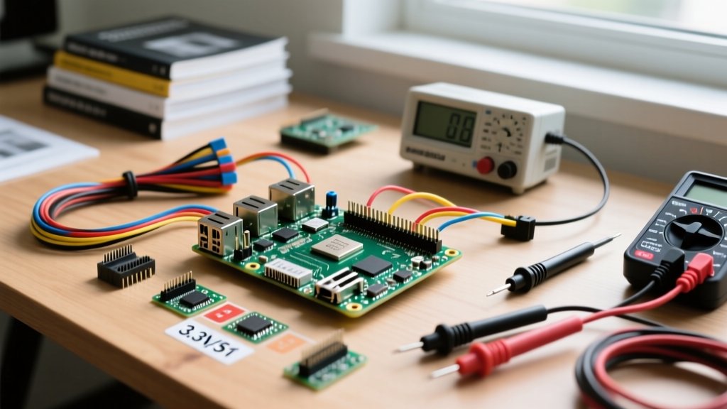
When integrating a Raspberry Pi into a broader maker ecosystem—especially alongside 5V microcontrollers like the Arduino Uno or Mega—understanding the physical and logical layout of the RPi GPIO pinout is your first critical step. Unlike the straightforward digital/analog mapping of an ATmega328P, the Raspberry Pi's 40-pin header multiplexes several high-speed peripheral buses alongside standard general-purpose I/O. Since the introduction of the 40-pin header on the Model B+, the physical layout has remained remarkably consistent, but the underlying silicon architecture has evolved dramatically, particularly with the RP1 I/O controller introduced in the Raspberry Pi 5.
Before writing a single line of Python or C++, you must decide on your numbering scheme. The Broadcom (BCM) numbering system references the internal SoC GPIO channels (e.g., GPIO17), while the Board (Physical) numbering references the literal pin position on the header (e.g., Pin 11). For hardware configuration and schematic design, we strongly recommend defaulting to BCM numbering, as it aligns with the official Raspberry Pi Official GPIO Documentation and prevents confusion when migrating code between different Pi models.
Critical Bus and Power Pin Mapping
Below is a configuration reference for the most frequently used pins when bridging a Raspberry Pi with external microcontrollers and sensors.
| BCM GPIO | Board Pin | Primary Function | Configuration Notes & Constraints |
|---|---|---|---|
| N/A | 1, 17 | 3.3V Power | Max draw varies by model. Do not use as a logic HIGH reference. |
| N/A | 2, 4 | 5V Power | Directly tied to USB-C input. Bypasses onboard regulators. |
| 2 (SDA1) | 3 | I2C Data | Features onboard 1.8kΩ pull-up resistors to 3.3V. |
| 3 (SCL1) | 5 | I2C Clock | Features onboard 1.8kΩ pull-up resistors to 3.3V. |
| 14 (TXD) | 8 | UART Transmit | Defaults to 3.3V. Requires level shifting for 5V MCU RX. |
| 15 (RXD) | 10 | UART Receive | Extremely sensitive. 5V input will destroy the SoC. |
| 10 (MOSI) | 19 | SPI0 MOSI | Master Out Slave In. Configure via SPI0 hardware block. |
| 9 (MISO) | 21 | SPI0 MISO | Master In Slave Out. Tolerates 3.3V input only. |
Voltage Translation: Interfacing 3.3V RPi with 5V MCUs
The most catastrophic failure mode in mixed-voltage maker projects is ignoring the logic level disparity. The Raspberry Pi operates strictly at 3.3V logic. Standard Arduinos (Uno, Nano, Mega) operate at 5V logic. If you connect a 5V Arduino TX pin directly to the Raspberry Pi's RX pin (GPIO 15 / Board Pin 10), the 1.7V excess will forward-bias the internal ESD clamping diodes on the Broadcom SoC. This forces current into the 3.3V rail, rapidly overheating the silicon and permanently bricking the board.
To safely configure your RPi GPIO pinout for 5V MCU communication, you must implement voltage translation. There are two primary hardware solutions we recommend based on signal frequency and directionality:
1. BSS138 MOSFET Bidirectional Level Shifters
For I2C buses and bidirectional UART lines, a BSS138 N-channel MOSFET level shifter is the gold standard. These breakout boards (often sold by SparkFun or Adafruit for around $2.95) utilize a clever pull-up and MOSFET gate-threshold circuit to safely translate 3.3V to 5V and vice versa without backfeeding. You configure the low-voltage (LV) side to the Pi's 3.3V pin and the high-voltage (HV) side to the Arduino's 5V pin. For a deep dive into the physics of this translation, refer to the SparkFun Logic Levels Tutorial.
2. CD4050BE Non-Inverting Hex Buffers
For high-speed, unidirectional signals (such as driving a 5V WS2812B LED data line from the Pi's GPIO 18), the CD4050BE buffer IC is superior. It accepts up to 15V on its VCC pin but will output a clean 5V signal when fed a 3.3V logic HIGH from the Pi, provided the VCC is tied to 5V. This is significantly cheaper than buying pre-built modules and allows for custom PCB integration.
Software Configuration: Mapping and Activating Pins
Once your hardware is safely wired, you must configure the software state of the pins. While Python libraries like RPi.GPIO or gpiozero are popular, they are being deprecated in favor of the modern libgpiod C library and the raspi-gpio debugging tool. For low-level configuration and persistent daemon setups, understanding the command-line interface is essential.
Using raspi-gpio for Pin State Verification
The raspi-gpio utility allows you to query and set pin states directly from the terminal, bypassing Python overhead. This is invaluable when troubleshooting hardware wiring before writing application code.
- Query Pin State:
raspi-gpio get 17(Returns current level, pull state, and function). - Set as Output:
raspi-gpio set 17 op(Configures GPIO 17 as an output). - Drive High:
raspi-gpio set 17 dh(Drives the pin to 3.3V). - Enable Pull-Down:
raspi-gpio set 17 pd(Activates the internal pull-down resistor, crucial for floating button inputs).
Enabling Hardware Peripherals via raspi-config
By default, the Raspberry Pi OS disables hardware buses to free up GPIO pins for standard I/O and to prevent boot conflicts. To configure the I2C or SPI buses for external MCU communication, you must enable them via the OS configuration tool:
- Open the terminal and type
sudo raspi-config. - Navigate to Interface Options.
- Select I2C or SPI and choose Yes to enable the kernel module.
- Reboot the system. Verify activation by running
lsmod | grep i2corspi.
Power Delivery Constraints and Backfeeding Risks
A common misconception among beginners is that the 3.3V and 5V pins on the RPi GPIO pinout can supply unlimited current to external breadboards. This is false and leads to brownouts, random reboots, and corrupted SD cards. The power architecture differs significantly between Pi generations.
Architectural Shift in Pi 5: The Raspberry Pi 4 utilized a linear LDO regulator for the 3.3V rail, limiting total available current to roughly 800mA before thermal throttling. The Raspberry Pi 5 upgraded to a dedicated buck converter, pushing the 3.3V rail capacity well over 2A. However, the individual GPIO pins on the RP1 chip are still strictly limited to a maximum of 16mA per pin, with a recommended continuous draw of just 3mA to 5mA to maintain signal integrity.
If your project requires driving high-current loads like relays, solenoids, or long LED strips, never source this current from the GPIO pins or even the 5V header if you are powering the Pi via a standard 3A USB-C supply. Instead, use a dedicated external 5V buck converter module (like an LM2596 set to 5.05V) to power your peripherals, ensuring you tie the external ground back to one of the Pi's GND pins (e.g., Board Pin 6) to establish a common ground reference.
The Danger of Backfeeding via the 5V Pins
Board Pins 2 and 4 provide direct access to the 5V USB-C input rail. Some advanced users 'backfeed' power into the Pi by applying 5.1V to these pins, bypassing the USB-C power delivery circuitry and polyfuse. While this reduces voltage drop, it is highly dangerous. If your external 5V supply exceeds 5.25V, or if you accidentally apply 12V, you will instantly destroy the Pi's power management IC (PMIC) and the SoC. We strongly advise against backfeeding in any configuration guide meant for general maker use.
Troubleshooting Common GPIO Configuration Errors
Even with perfect wiring, software configuration errors can halt your project. Here are the most common issues encountered when mapping the RPi GPIO pinout:
1. 'Permission Denied' on /dev/mem or /dev/gpiomem
If your Python script or C program throws a memory access error, your user lacks the correct group permissions. Modern Raspberry Pi OS routes GPIO access through /dev/gpiomem, which is owned by the gpio group. Ensure your user is added to this group by running sudo usermod -aG gpio $USER, then log out and log back in. Avoid running GPIO scripts with sudo unless absolutely necessary, as this introduces severe security vulnerabilities and can mess up file ownership in your home directory.
2. Pin State Retention After Reboot
Unlike an Arduino, which retains its last flashed sketch in EEPROM/Flash, the Raspberry Pi's GPIO pins reset to a high-impedance input state (with specific default pull-ups/downs defined by the SoC boot ROM) every time the device reboots. If your project requires a pin to be HIGH immediately upon power application (e.g., to keep a relay disengaged), you must configure a systemd service to run your initialization script at boot, or use a hardware pull-up resistor to define the default state before the OS loads.
3. I2C Bus Lockups and Missing Addresses
When running i2cdetect -y 1, you might see empty spaces or the bus might freeze. This is almost always a hardware issue, not a software one. Verify that your external MCU or sensor has a common ground with the Pi. Furthermore, if you are connecting multiple devices, the combined capacitance on the SDA/SCL lines might be overwhelming the Pi's internal 1.8kΩ pull-up resistors. In this case, add external 4.7kΩ pull-up resistors to the 3.3V rail to sharpen the signal rise times.
Mastering the RPi GPIO pinout configuration requires a synthesis of hardware respect and software precision. By honoring the 3.3V logic limits, utilizing proper level translation, and leveraging modern CLI tools for state verification, you can reliably integrate the Raspberry Pi into any complex microcontroller ecosystem. For a visual, interactive reference while wiring your next project, keep the Pinout.xyz interactive map bookmarked in your browser.