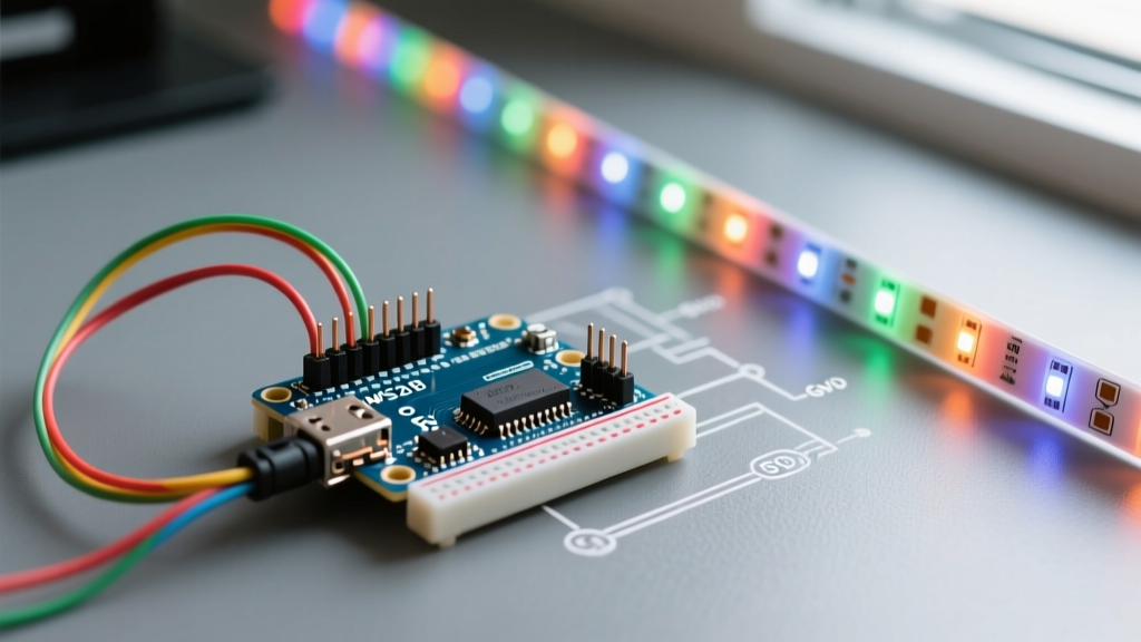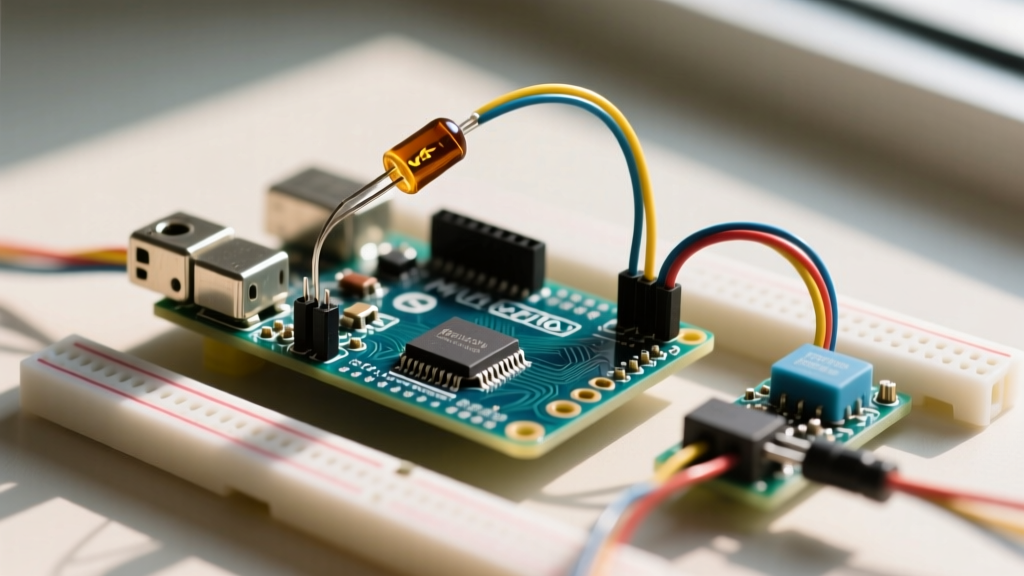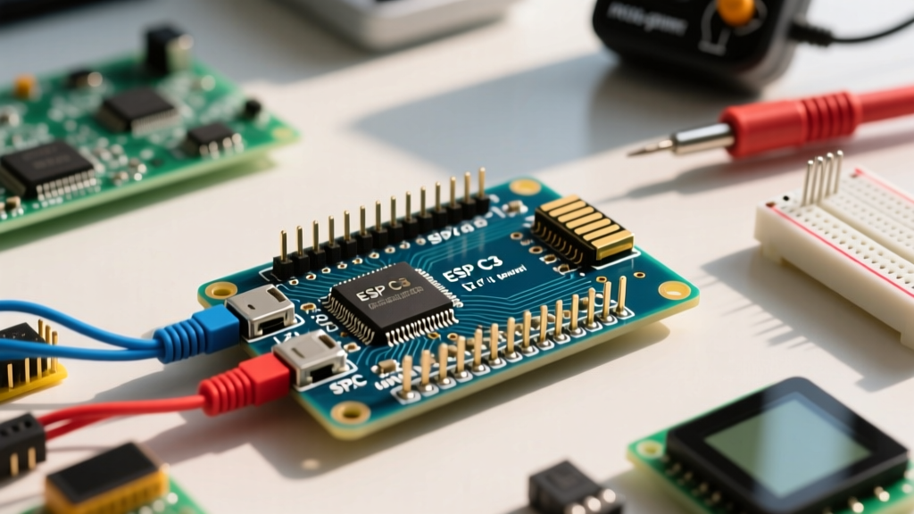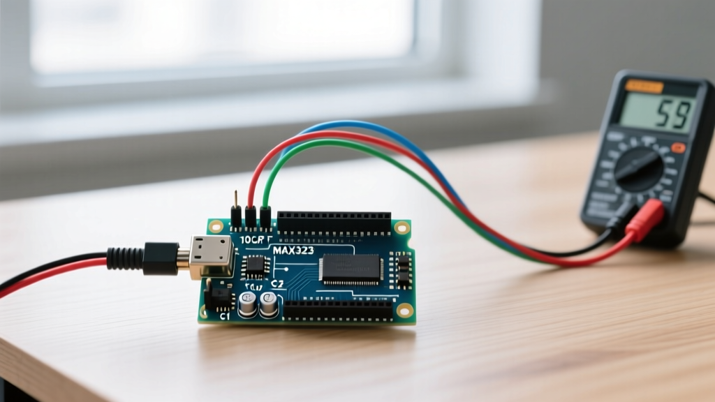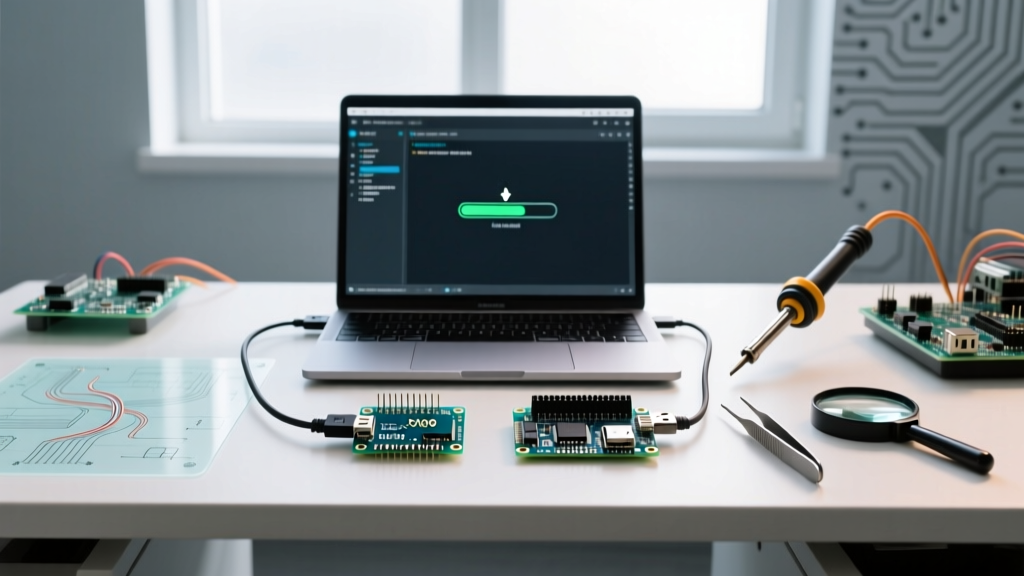

The pursuit of the tiniest Arduino form factor has driven makers toward ultra-compact microcontrollers like the ATtiny85-based Digispark clones (measuring just 18.5 x 15.2mm) and the modern Seeed XIAO RP2040 (21 x 17.5mm). While these micro-boards are exceptional for wearables, drones, and cramped enclosures, their minimal physical footprint strips away the robust voltage regulation, dedicated USB-to-Serial bridge chips, and bulk capacitance found on standard-sized boards like the Uno or Nano.
In 2026, a generic ATtiny85 Digispark clone costs between $2.50 and $3.50, while the Seeed XIAO RP2040 retails for roughly $4.99. However, the low financial cost is often offset by a high troubleshooting tax. The lack of hardware abstraction layers and minimal USB stacks results in a unique ecosystem of upload failures, bootloader timeouts, and power brownouts. This guide provides deep-level error diagnosis and actionable hardware fixes for the most common faults encountered when programming the tiniest Arduino platforms.
1. The ATtiny85 (Digispark) USB Stack & Bootloader Nightmares
The Digispark does not use a dedicated serial-to-USB chip. Instead, it relies on the Micronucleus bootloader, which implements USB directly via software interrupts on the ATtiny85's limited pins. This architectural shortcut is the root cause of the most infamous upload errors in the maker community.
Error: micronucleus: warning: could not find device
This error occurs when the Arduino IDE compiles successfully but fails to handshake with the board via USB (VID: 16D0, PID: 0753). On Windows 11, this is almost always a driver signature or polling issue, not a dead board.
Critical Timing Constraint: The Micronucleus bootloader only listens for a USB connection for exactly 60 seconds after power is applied. If you plug the board in before the IDE prompts you, the bootloader will time out and jump to the user sketch, ignoring the upload command.
The Diagnosis & Fix Protocol
- Driver Replacement: Download the Zadig USB Driver Tool. Plug in the Digispark, open Zadig, select 'libusb0' or 'Unknown Device' from the dropdown, and replace the driver with libusbK (v3.0.7.0 or newer). The default Windows WinUSB driver frequently drops the short USB enumeration packets sent by the ATtiny85.
- USB 3.0 Hub Polling: If using a modern USB-C hub, the host controller's polling rate may miss the software-emulated USB packets. Always plug the Digispark directly into a motherboard USB 2.0 port or use an externally powered USB 2.0 hub.
- The 'Plug-In' Dance: Click 'Upload' in the IDE. Wait for the console to read
Running Digispark Uploader... Plug in device now. Only then insert the board into the USB port.
2. Seeed XIAO RP2040 Bootloader & Pin Mapping Faults
The Seeed XIAO series represents the modern iteration of the tiniest Arduino concept, packing a dual-core ARM Cortex-M0+ (RP2040) into a 21 x 17.5mm footprint with castellated edge pads. While it features a native, hardware-accelerated USB stack, its microscopic reset mechanisms often confuse users transitioning from standard Nano boards.
Error: No DFU capable USB device available or Port Greyed Out
This occurs when a poorly written sketch crashes the USB stack (e.g., flooding Serial.print() without a connected monitor, or triggering a watchdog reset loop), preventing the RP2040 from enumerating as a COM port or UF2 drive.
Hardware Recovery: The BOOTSEL Pad Short
The XIAO RP2040 lacks a physical reset button. To force the MCU into its native UF2 bootloader mode, you must manipulate the hardware pads directly.
- Locate the two gold pads labeled BOOTSEL and GND on the underside or edge of the PCB.
- Using fine-tipped ceramic tweezers, short these two pads together.
- While maintaining the short, plug the USB-C cable into your PC.
- Release the tweezers. The board will mount as a 128MB removable flash drive named
RPI-RP2. - Drag and drop your compiled
.uf2file directly onto the drive. For Arduino IDE users, selecting the correct COM port will now allow standard uploads to resume.
For comprehensive pin-mapping and board manager configurations, refer to the official Seeed Studio XIAO RP2040 Wiki.
3. The Hidden Killer: Power Brownouts & Memory Overflows
When your sketch uploads successfully but the tiny Arduino exhibits random reboots, garbage serial output, or erratic sensor readings, you are likely facing a power brownout. The tiniest Arduino boards sacrifice bulk capacitance to maintain their footprint. A standard Digispark features only a 100nF decoupling capacitor and a 10uF bulk capacitor on the 5V rail.
If you attempt to drive an SSD1306 OLED display or a micro-servo directly from the 5V pin, the inrush current will cause the voltage rail to dip below the ATtiny85's Brown-Out Detection (BOD) threshold (typically set to 4.3V by default). The MCU instantly resets, often corrupting the EEPROM or causing the IDE to report an avrdude: verification error if the reset occurs during a write cycle.
Diagnostic Matrix: Tiny Arduino Errors
| Error Symptom | Target Board | Root Cause | Hardware / Software Fix |
|---|---|---|---|
avrdude: verification error, first mismatch |
ATtiny85 (Digispark) | VCC brownout during flash write cycle; BOD threshold too high. | Power via external 5V/2A supply; lower BOD fuse to 2.7V via ISP. |
| Sketch uploads, but board loops/reboots every 2 seconds | XIAO RP2040 / ATtiny85 | USB stack crash due to missing serial handshake or WDT timeout. | Add while(!Serial); guard; disable WDT in setup(). |
| IDE reports 'Programmer not responding' on custom ATtiny13 | Bare ATtiny13/85 | Fuses set to external crystal, but no crystal is attached. | Use High-Voltage Serial Programmer (HVSP) to reset fuses. |
| Garbage characters in Serial Monitor (e.g., '????') | ATtiny85 (SoftwareSerial) | Internal 8MHz oscillator drift; baud rate mismatch. | Tune OSCCAL register; use 4800 baud instead of 9600. |
4. ISP Recovery: Unbricking the Tiniest MCU
If you have accidentally corrupted the fuse bits on an ATtiny85 (for example, by enabling an external clock source when none is present), the software bootloader is permanently disabled. The board will appear completely dead to USB. You must recover it using In-System Programming (ISP).
The Arduino ISP Documentation outlines how to use a standard Uno as a programmer, but the physical connection to the tiniest Arduino requires precision. Because the ATtiny85 lacks a standard 6-pin ICSP header, you must probe the SOIC-8 chip or castellated pads directly.
ATtiny85 ISP Pinout Mapping
- MOSI: PB0 (Pin 5)
- MISO: PB1 (Pin 6)
- SCK: PB2 (Pin 7)
- RESET: PB5 (Pin 1)
- VCC: Pin 8 (Provide 5V from programmer)
- GND: Pin 4
Step-by-Step Fuse Recovery
- Wire your Arduino Uno (loaded with the ArduinoISP sketch) to the ATtiny85 pads using pogo pins or a SOIC-8 test clip.
- Open the Arduino IDE, select Tools > Programmer > Arduino as ISP.
- Select Tools > Burn Bootloader. This command does not just install a bootloader; it writes the default fuse bytes to the ATtiny85, resetting the clock source to the internal 8MHz PLL and disabling the external crystal requirement.
- Once the IDE reports 'Done burning bootloader', disconnect the ISP wires and test the USB upload via Micronucleus.
Conclusion
Working with the tiniest Arduino platforms requires a shift in diagnostic thinking. You are no longer just debugging code; you are debugging the physical limitations of USB enumeration, microscopic capacitance, and internal oscillator drift. By mastering driver-level interventions like Zadig, understanding the hardware BOOTSEL pad mechanics of the XIAO series, and maintaining an ISP recovery rig on your bench, you can reliably deploy micro-MCUs into the most demanding, space-constrained projects of 2026 and beyond.