
The Community Standard: Mastering the HC-SR04 Ultrasonic Sensor
If you have spent more than a week in the maker community, you have likely encountered the HC-SR04. Frequently misspelled in search engines and forum posts as the "hc sro4 arduino" setup, this 40kHz ultrasonic distance sensor remains the undisputed king of budget-friendly spatial awareness. Priced around $1.50 to $2.50 in 2026, it is the default choice for robotics, tank level monitoring, and proximity alarms.
However, the gap between a basic tutorial and a reliable, production-ready deployment is vast. This community resource roundup synthesizes years of forum debates, GitHub issue threads, and hardware hacks to elevate your HC-SR04 Arduino projects from fragile prototypes to robust systems.
HC-SR04 Core Specifications:- Operating Voltage: 5V DC (15mA working current)
- Measuring Angle: 15 degrees (effective beam width)
- Range: 2cm to 400cm (theoretical), practically 2cm to 350cm
- Trigger Pulse: 10µs TTL
- Echo Output: 5V TTL pulse proportional to distance
Why the Community Abandoned pulseIn()
The standard Arduino tutorial for the HC-SR04 relies on the built-in pulseIn() function. While functional for blinking an LED when an object gets close, pulseIn() is a blocking function. It halts your microcontroller's execution while waiting for the echo pin to go HIGH and then LOW, with a default timeout of one second. In a robotic navigation loop running at 50Hz, a one-second blocking delay is catastrophic.
The Gold Standard: NewPing Library
The community consensus overwhelmingly favors Tim Eckel’s NewPing library. Unlike basic wrappers, NewPing utilizes timer interrupts to read the echo pin asynchronously. This frees up your main loop to handle motor control, PID calculations, or wireless communication without stuttering.
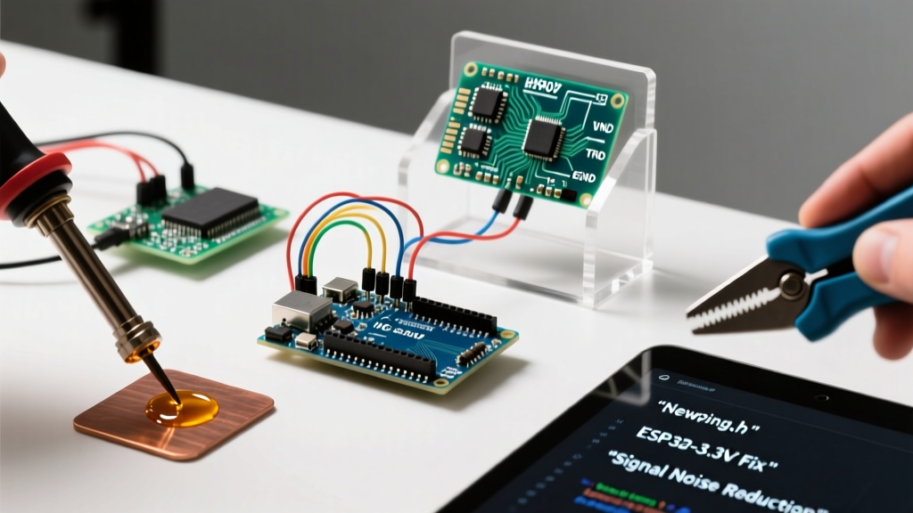
Pro-Tip from the Forums: NewPing defaults to using Timer2 on AVR boards (like the Uno or Nano). If your project also uses the Tone library or certain IR remote libraries, you will encounter a Timer2 conflict. The community fix is to edit the NewPing.h file and change the timer definition, or switch to an event-driven polling method using micros() if you are strictly opposed to library dependencies.
Hardware Hacks: Eliminating Ghost Readings
A frequent complaint on the Arduino forums is "ghost readings"—sudden spikes showing 400cm or 0cm when the environment hasn't changed. This is rarely a faulty sensor; it is usually an acoustic or electrical noise issue.
1. The 0.1µF Decoupling Capacitor Fix
The HC-SR04 draws sudden bursts of current (up to 20mA) when firing the ultrasonic transducers. On long, thin jumper wires, this causes a localized voltage drop on the VCC line, which resets the sensor's internal logic or corrupts the echo timing. Soldering a 0.1µF ceramic capacitor directly across the VCC and GND pins on the back of the sensor module stabilizes the power delivery and eliminates 80% of erratic spikes.
2. Acoustic Cross-Talk in Multi-Sensor Arrays
Building a rover with four HC-SR04 sensors? If you trigger them simultaneously, the echo from Sensor A will bounce off a wall and be read by Sensor B, resulting in false proximity alerts. The community-established protocol is sequential pinging with a 29ms delay between each sensor trigger. This 29ms window ensures that any residual acoustic echoes from the previous ping have dissipated below the sensor's detection threshold before the next 40kHz burst is emitted.
Custom PCB Design: Routing for the HC-SR04
When transitioning from a breadboard prototype to a custom PCB, the physical placement of the HC-SR04 footprint is critical. The community has documented numerous cases where sensors failed due to acoustic feedback through the PCB substrate. If you mount the sensor flush against the board, the 40kHz vibrations can couple into the fiberglass, creating phantom echoes. The established best practice is to use right-angle pin headers to mount the sensor facing outward, away from the board plane, or to use a 4-pin JST-SH connector with twisted-pair wiring to keep the acoustic transducers completely isolated from the main control board.
Furthermore, ensure your VCC traces are sufficiently wide. A standard 10mil trace might introduce too much resistance over a 10cm run, exacerbating the voltage drop during the 20mA transmit burst. Use at least a 20mil trace for the 5V and GND lines feeding the ultrasonic module, and place the 0.1µF decoupling capacitor as close to the sensor footprint as physically possible.
Community Waterproofing Hacks for the Standard Module
While the JSN-SR04T is the official waterproof variant, budget constraints sometimes force makers to deploy the standard HC-SR04 in damp environments like greenhouse soil monitors or outdoor weather stations. A popular community hack involves carefully removing the metal mesh grilles from the transducers, applying a thin layer of acoustic-transparent conformal coating directly to the piezoelectric diaphragms, and replacing the mesh with a piece of tightly stretched nylon stocking. This prevents water droplets from bridging the mesh wires—which detunes the resonant frequency—while allowing the 40kHz sound waves to pass with minimal attenuation.
3.3V Logic Integration: ESP32 and RP2040
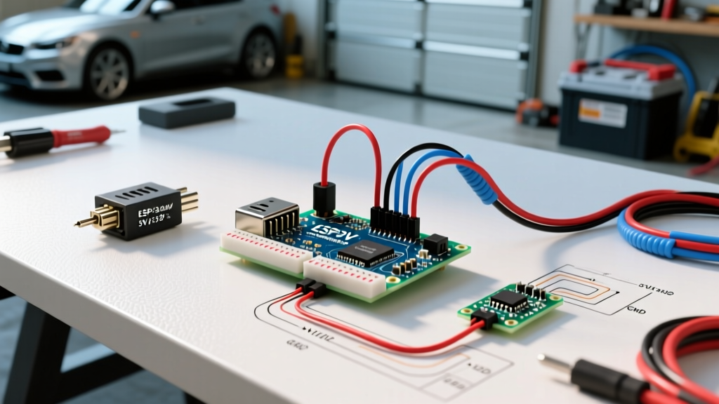
As the maker community shifts toward 3.3V microcontrollers like the ESP32 and Raspberry Pi Pico (RP2040), the HC-SR04 presents a critical hardware mismatch. The sensor's Echo pin outputs a 5V TTL signal. Feeding 5V directly into an ESP32 GPIO pin will eventually degrade or destroy the silicon.
The Voltage Divider Solution
To safely interface the 5V Echo pin with a 3.3V microcontroller, the community standard is a simple resistor voltage divider. You will need a 2kΩ resistor (R1) and a 1kΩ resistor (R2).
- Connect the HC-SR04 Echo pin to one end of the 2kΩ resistor.
- Connect the other end of the 2kΩ resistor to your ESP32 GPIO pin.
- Connect the 1kΩ resistor between that same GPIO pin and the system GND.
This configuration steps the 5V pulse down to approximately 3.33V, safely within the ESP32's tolerance. Note: The Trigger pin only requires a 3.3V input to register a HIGH state on the HC-SR04, so you can wire the Trigger pin directly to the ESP32 without a level shifter.
Sensor Variant Comparison Matrix
The original HC-SR04 has spawned several variants to address specific environmental limitations. Here is how the community evaluates the current ecosystem in 2026:
| Model | Logic Level | Environment | Max Range | Avg. Cost (2026) |
|---|---|---|---|---|
| HC-SR04 | 5V Only | Indoor / Dry | 400cm | $1.50 - $2.00 |
| HC-SR04P | 3.3V & 5V | Indoor / Dry | 400cm | $2.50 - $3.50 |
| JSN-SR04T | 5V Only | Outdoor / Wet (IP67) | 450cm | $6.00 - $9.00 |
| A02YYUW | 3.3V - 5V (UART) | Outdoor / Wet (IP67) | 450cm | $12.00 - $15.00 |
Note: If your project involves high humidity or condensation, skip the standard HC-SR04. Water droplets on the mesh grille detune the 40kHz acoustic resonance, causing permanent read failures until dried.
Advanced Edge Cases & Troubleshooting
The "Soft Material" Absorption Problem
Ultrasonic sensors rely on acoustic reflection. If your robot is navigating a room with heavy curtains, foam acoustic panels, or plush carpets, the 40kHz waves will be absorbed rather than reflected. The sensor will report maximum distance (timeout) even when an object is 20cm away. The community workaround for this edge case is sensor fusion: pairing the HC-SR04 with a Sharp IR sensor (like the GP2Y0A21YK0F), which uses light and is unaffected by acoustic absorption.
Temperature Compensation
The speed of sound is not a constant 343 m/s; it fluctuates with ambient temperature. At 0°C, sound travels at 331 m/s, while at 30°C, it travels at 349 m/s. For a 400cm measurement, this variance introduces an error of roughly 8cm. If your Arduino project requires millimeter-level precision across varying seasons, the community recommends wiring a DS18B20 temperature sensor alongside the HC-SR04 and applying the formula: Speed = 331.3 + (0.606 * Temperature_C) to dynamically adjust your distance calculations in the sketch.
Summary
The HC-SR04 remains a staple of the Arduino ecosystem for good reason. By moving beyond basic pulseIn() tutorials, implementing hardware decoupling, utilizing asynchronous libraries like NewPing, and respecting 3.3V logic boundaries, you can extract highly reliable spatial data from this inexpensive module. Always consult component datasheets and community repositories like Components101 for baseline electrical characteristics before finalizing your PCB layout.