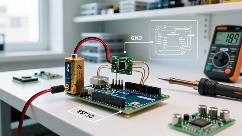

Building a custom Arduino heat pump controller is a highly rewarding intermediate-to-advanced maker project. While commercial smart thermostats like the Ecobee SmartThermostat or Nest Learning Thermostat handle standard residential split systems, they fall short when managing custom dual-fuel setups, variable-speed compressor staging, or experimental geothermal loops. By configuring an Arduino Mega 2560 as the brain, you gain granular control over the reversing valve, compressor contactor, and blower logic.
However, controlling a heat pump involves switching high-current inductive loads (compressors) and managing significant thermal lag. According to the U.S. Department of Energy, improper staging and short-cycling can reduce a heat pump's lifespan by up to 40% and severely degrade its Seasonal Energy Efficiency Ratio (SEER). This configuration guide details the exact hardware, wiring isolation techniques, and PID tuning required to build a safe, reliable Arduino heat pump controller.
Core Hardware Bill of Materials (BOM)
To handle the I/O requirements of a standard split-system heat pump (compressor, reversing valve, indoor blower, outdoor fan, and multiple temperature sensors), the Arduino Uno is insufficient. We recommend the Arduino Mega 2560 for its abundant digital pins and hardware serial ports.
| Component | Recommended Model | Est. Cost | Purpose |
|---|---|---|---|
| Microcontroller | Arduino Mega 2560 Rev3 | $28 - $35 | Main logic and PID processing |
| Temperature Sensors | DS18B20 Waterproof (x3) | $12 (pack) | Ambient, Coil, and Discharge temp monitoring |
| Compressor Contactor | Packard C40A (40A, 24VAC Coil) | $22 - $28 | Switching the high-voltage compressor load |
| Isolation Relay Module | 4-Channel 5V Optocoupler Relay | $6 - $9 | Galvanic isolation between 5V logic and 24VAC |
| Snubber Circuit | 100Ω Resistor + 0.1μF Capacitor | < $2 | Back-EMF suppression for contactor coils |
Wiring Architecture & Galvanic Isolation
The most common point of failure in DIY HVAC controllers is electromagnetic interference (EMI) and back-electromotive force (Back-EMF). When a contactor coil de-energizes, the collapsing magnetic field generates a high-voltage spike that can instantly fry your Arduino's ATmega2560 chip or cause erratic resets.
Step 1: Implement Optocoupler Isolation
Never wire the Arduino's 5V digital pins directly to a 24VAC HVAC control board or contactor coil. Use a 5V optocoupler relay module. The Arduino triggers the low-current LED inside the optocoupler, which optically triggers the phototransistor to switch the 24VAC circuit. This ensures galvanic isolation—meaning there is no direct electrical connection between your high-voltage HVAC system and your low-voltage microcontroller.
Step 2: Install RC Snubber Networks
Even with optocouplers, EMI can radiate through the air and induce noise on your sensor lines. Solder an RC snubber (a 100-ohm resistor in series with a 0.1μF X2-rated capacitor) directly across the terminals of the Packard C40A contactor coil. This absorbs the inductive kickback and protects your logic boards.
Expert Warning: Always adhere to local electrical codes when wiring line-voltage components. The NFPA 70 (National Electrical Code) strictly mandates proper grounding, enclosure bonding, and overcurrent protection for all HVAC control circuits. Never leave 120V/240V splices exposed outside of a rated NEMA enclosure.
Power Supply Architecture for the Controller
Powering an Arduino Mega and a 4-channel relay module from a standard USB wall-wart is a recipe for instability in an HVAC environment. The 24VAC control transformer (usually a 40VA Class 2 transformer located in the indoor air handler) is the most reliable power source.
Use an isolated AC-to-DC buck converter module (such as the Hi-Link HLK-PM01 or a dedicated 24VAC to 5VDC HVAC power supply board) to step down the 24VAC to a clean 5VDC. Ensure the 5VDC rail can supply at least 1.5A to handle the Arduino, the DS18B20 sensors, and the optocoupler LEDs simultaneously. Add a 1000μF electrolytic capacitor across the 5V and GND rails on your custom PCB or perfboard to smooth out voltage transients caused by the blower motor starting up.
Sensor Calibration & Noise Mitigation
For an Arduino heat pump controller, accurate temperature reading is non-negotiable. The PID loop relies on precise delta-T calculations to decide when to engage the compressor or switch to auxiliary electric resistance heat.
- Sensor Choice: Avoid analog NTC thermistors for long cable runs. The resistance of the copper wire will skew your readings. Instead, use digital DS18B20 sensors communicating over the 1-Wire protocol.
- Wiring Topology: Wire the DS18B20 sensors in external power mode (VDD to 5V, GND to GND, Data to Pin 22). Do not use parasitic power mode for HVAC applications, as the current draw during temperature conversion can cause voltage sags on long runs.
- Pull-up Resistor: A 4.7kΩ pull-up resistor on the data line is mandatory. For runs exceeding 10 meters, drop this to a 2.2kΩ resistor to strengthen the signal edge and prevent CRC checksum errors.
Configuring the PID Control Loop
Standard thermostats use simple hysteresis (bang-bang control): turn on at 68°F, turn off at 70°F. Heat pumps, however, perform best when maintaining a steady state to maximize the Coefficient of Performance (COP). We utilize the Arduino PID Library by Brett Beauregard to manage proportional heating and cooling.
Tuning for Thermal Mass
HVAC systems possess massive thermal lag. The air temperature at the sensor doesn't change instantly when the compressor engages. If your Integral (Ki) and Derivative (Kd) gains are too high, the system will suffer from integral windup, causing severe overshoot and short-cycling.
Start your configuration with these conservative baseline values for a standard 3-ton residential air-source heat pump:
- Kp (Proportional): 2.5
- Ki (Integral): 0.08
- Kd (Derivative): 1.2
- Sample Time: 5000ms (5 seconds). Do not sample faster; thermal mass makes sub-second adjustments useless and introduces noise into the derivative calculation.
Critical Safety Interlocks & Failure Modes
Software logic can crash, freeze, or enter an infinite loop. Therefore, life-safety and equipment-protection interlocks must be hardwired, bypassing the Arduino entirely.
Hardware Anti-Short Cycle Protection
While your Arduino sketch should enforce a 5-minute minimum off-time before restarting the compressor, you should also wire a physical time-delay relay (e.g., an ICM Controls ICM203) in series with the contactor coil. If the Arduino reboots and accidentally commands the compressor on immediately after a power flicker, the hardware time-delay will physically block the 24VAC signal, saving your compressor from catastrophic mechanical failure due to unequalized refrigerant pressures.
Pressure Switch Integration
Wire the high-pressure and low-pressure safety switches directly in series with the 24VAC contactor coil before it reaches your Arduino's relay. If refrigerant pressure spikes due to a blocked condenser coil or a failed outdoor fan motor, the mechanical switch will drop the contactor instantly, regardless of what the Arduino's code is doing.
Frequently Asked Questions
Can an Arduino handle a variable-speed (inverter) heat pump compressor?
Directly controlling a proprietary inverter compressor (like those in Mitsubishi Hyper-Heat or Daikin VRV systems) is generally not feasible via basic Arduino I/O. These require high-speed CAN bus or proprietary serial communication to the inverter board. An Arduino is best suited for single-stage or two-stage standard scroll/reciprocating compressors where you are simply switching the main contactor.
How do I handle the reversing valve logic?
Most American heat pumps (e.g., Rheem, Ruud) energize the 24VAC reversing valve solenoid for cooling. Most Asian and European models (e.g., Daikin, Mitsubishi) energize it for heating. Your Arduino code must include a boolean configuration flag (REV_VALVE_ON_COOL = true/false) to match your specific outdoor unit's O/B terminal logic. Getting this backwards will result in the system heating when you call for cooling, which can lead to dangerous head-pressure spikes if the indoor coil is not prepared to act as a condenser.