
The Anatomy of a Missing PPS Interrupt
The Pulse Per Second (PPS) signal is the holy grail of precision timing in embedded systems. While standard NMEA sentences over UART provide time data, they suffer from variable latency due to serial buffer processing and baud rate transmission delays. The hardware PPS pin, however, outputs a physical logic pulse aligned to the UTC second edge with sub-microsecond jitter. When integrating an Arduino GPS PPS setup, makers frequently encounter a frustrating scenario: the GPS achieves a 3D fix, NMEA sentences stream perfectly, but the PPS interrupt never fires, or worse, fires erratically.
Diagnosing this requires separating hardware signal integrity issues from software Interrupt Service Routine (ISR) bottlenecks. In 2026, with the widespread adoption of multi-band modules like the u-blox ZED-F9P and the Arduino Uno R4 Minima, the classic troubleshooting steps for older 5V logic boards must be updated. This guide provides a deep-dive diagnostic framework for resolving PPS signal loss, phantom interrupts, and timing drift.
Hardware Diagnosis: Voltage Thresholds and Pull-up Failures
The most common cause of a missing PPS signal is a logic level mismatch compounded by poor noise margins. Most modern GPS modules, including the popular NEO-M8N and the high-precision ZED-F9P (typically priced between $160 and $220 depending on the antenna bundle), operate on 3.3V logic. The PPS output pin is usually driven to 3.3V during the active pulse.
The 5V Arduino Threshold Problem
If you are using a classic 5V Arduino Uno R3 or Mega 2560 (based on the ATmega328P or ATmega2560), the microcontroller requires a minimum Input High Voltage (V_IH) of 0.6 × VCC. On a 5V system, this means the pin requires at least 3.0V to reliably register a HIGH state. A 3.3V PPS signal leaves a noise margin of only 0.3V. Any electromagnetic interference (EMI) from the GPS module's internal switching DC-DC buck converter can easily pull the signal below the threshold, causing the Arduino to miss the interrupt entirely.
The Fix: Use a bidirectional logic level shifter (like a BSS138-based MOSFET board, costing around $3) to translate the 3.3V PPS pulse to a clean 5V pulse. Alternatively, migrate to a 3.3V native microcontroller like the Teensy 4.1 or the Arduino Nano 33 IoT, where a 3.3V pulse is natively recognized as a robust HIGH.
The 'Floating Pin' and Phantom Interrupts
Many breakout boards route the PPS pin directly from the GPS chip without an onboard pull-up resistor. If the GPS module is in a low-power state or has not yet achieved a time fix, the PPS pin may be high-impedance (floating). A floating pin acts as an antenna, picking up stray RF energy and triggering hundreds of phantom interrupts per second.
The Fix: Always install a 10kΩ external pull-up resistor between the PPS pin and the microcontroller's logic voltage (3.3V or 5V, matching your system). This ensures the line is held firmly HIGH when the GPS is not actively pulling it LOW, and provides a clean rising edge when the pulse begins.
Module Specifications and PPS Characteristics
Understanding the default behavior of your specific module is critical for configuring your oscilloscope or logic analyzer during diagnosis. Below is a comparison of common modules used in maker projects.
| GPS Module | Logic Level | Default PPS Width | Typical Price (2026) | Configuration Interface |
|---|---|---|---|---|
| u-blox NEO-6M | 3.3V | 100ms | $12 - $18 | UBX Protocol |
| u-blox NEO-M8N | 3.3V | 100ms | $20 - $35 | UBX Protocol |
| u-blox ZED-F9P | 3.3V | 100ms (Configurable) | $160 - $220 | UBX / RTCM |
| Quectel L80-R | 3.3V (Open Drain) | 50ms | $25 - $40 | PMTK / NMEA |
Note: Modules with open-drain PPS outputs (like the Quectel L80) absolutely require an external pull-up resistor to function.
Software Diagnosis: ISR Bottlenecks and Volatile Variables
If your hardware signal is clean (verified via a logic analyzer showing a sharp rising edge), the failure lies in the firmware. The Arduino attachInterrupt() function is powerful, but easily misused in timing-critical applications.
The Fatal Error: Serial Printing Inside an ISR
The most frequent beginner mistake is placing a Serial.println() or digitalWrite() command inside the PPS Interrupt Service Routine. ISRs must execute in microseconds. Serial communication relies on its own background interrupts to shift bits out of the UART buffer. If you call Serial inside an ISR, you create a deadlock or severely delay the ISR, causing the microcontroller to miss subsequent timing events or corrupt memory.
// INCORRECT: Will cause timing drift and potential system lockups
void pps_isr() {
  Serial.println('PPS Triggered!');
  pulse_time = micros();
}

// CORRECT: Minimal ISR with volatile flag
volatile unsigned long pps_micros = 0;
volatile bool pps_flag = false;

void pps_isr() {
  pps_micros = micros();
  pps_flag = true;
}
Variable Volatility and Memory Barriers
Any variable modified inside the ISR and read in the main loop() must be declared with the volatile keyword. This instructs the compiler not to cache the variable in a CPU register, ensuring the main loop always reads the fresh value from SRAM. Furthermore, when reading multi-byte variables (like a 32-bit unsigned long from micros()) on an 8-bit AVR Arduino, you must temporarily disable interrupts to prevent a partial read if the ISR fires mid-read.
Edge Case: Timer Conflicts and Microsecond Drift
According to the National Institute of Standards and Technology (NIST), GPS disciplined oscillators rely on the PPS signal to correct the inherent drift of local quartz crystals. On an Arduino, the micros() function is tied to Timer0, which increments every 4µs on a 16MHz board. This means your PPS timestamp will always be quantized to a 4µs resolution.
If you are building a high-precision clock synchronized to the US Naval Observatory's GPS time standards, a 4µs quantization error might be unacceptable. To bypass this, advanced users configure a dedicated hardware timer (like Timer1 or Timer2) to count raw CPU cycles (62.5ns resolution on a 16MHz board) and read that timer's register directly inside the PPS ISR, completely bypassing the micros() abstraction.
Step-by-Step Troubleshooting Matrix
Use this diagnostic matrix to isolate your specific failure mode.
| Symptom | Probable Cause | Diagnostic Action & Solution |
|---|---|---|
| ISR never triggers, flag remains false. | PPS disabled in GPS firmware or wrong pin mapping. | Connect via U-Center. Check CFG-TP5 settings to ensure Timepulse is enabled. Verify digitalPinToInterrupt() mapping. |
| ISR triggers hundreds of times per second. | Floating PPS pin picking up EMI. | Probe with oscilloscope. Add 10kΩ pull-up resistor to VCC. Ensure ground wire is short and thick. |
| ISR triggers, but timestamp drifts by milliseconds. | Blocking code in main loop delaying flag processing. | Remove delay() from main loop. Use non-blocking state machines. Process pps_flag immediately at the top of loop(). |
| System freezes or reboots when GPS achieves fix. | Serial buffer overflow or ISR deadlock. | Remove all Serial prints from ISR. Ensure I2C/SPI operations are not occurring inside the interrupt context. |
Advanced Sync: Configuring u-blox Timepulse (CFG-TP5)
Out of the box, u-blox modules output a PPS signal that is referenced to the internal oscillator, which is only disciplined to GPS time once a valid 3D fix and time solution are acquired. If you are diagnosing a system where the PPS pulse width seems wrong (e.g., 10ms instead of 100ms), you must interface with the module's UBX protocol.
Using the u-blox U-Center software or a library like SparkFun u-blox GNSS Arduino Library, navigate to the Timepulse settings (CFG-TP5). Here, you can define the pulse ratio, the grid alignment (UTC vs. GPS time), and the behavior before and after a time fix. A common error is leaving the module in 'GPS Time' mode while your NMEA parser expects 'UTC Time', resulting in a PPS edge that is offset by the current number of leap seconds (18 seconds as of 2026). Always verify your leap second handling in both the GPS configuration and your Arduino parsing logic.
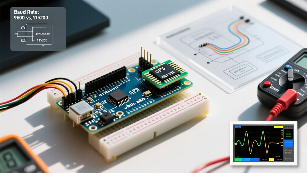
Expert Tip: When probing the PPS pin with an oscilloscope, trigger on the rising edge and set the timebase to 500ms/division. You should see a perfectly periodic square wave. If the rising edge looks 'fuzzy' or exhibits ringing, your ground lead inductance is too high, or the GPS module's LDO is struggling under the load of the RF front-end. Decoupling the GPS VCC pin with an additional 100µF tantalum capacitor can stabilize the PPS output driver.
Conclusion
Diagnosing an Arduino GPS PPS failure requires a methodical approach that bridges RF hardware realities and strict embedded software constraints. By ensuring proper logic level translation, eliminating floating pins with pull-up resistors, and writing lean, non-blocking Interrupt Service Routines, you can transform a standard microcontroller into a highly accurate, GPS-disciplined timing node. Always validate your physical layer with a logic analyzer before rewriting firmware, as 90% of PPS errors originate in the wiring.