
The Anatomy of a 10K Potentiometer in Microcontroller Circuits
At its core, a potentiometer (or "pot") is a three-terminal resistor with a sliding or rotating contact that forms an adjustable voltage divider. When makers refer to an Arduino 10K pot, they are typically describing a 10,000-ohm variable resistor used to feed a variable analog voltage into a microcontroller's Analog-to-Digital Converter (ADC) pin. While it seems like a trivial component, misunderstanding the electrical physics of the 10K potentiometer is one of the most common reasons for erratic sensor readings, ghosting values, and non-linear mapping in embedded projects.
In 2026, standard through-hole carbon track potentiometers like the Bourns PTV09A series or the Alpha RD901F remain the workhorses of DIY electronics, typically costing between $1.20 and $2.50 per unit depending on the shaft style and taper. However, selecting the correct resistance value and taper is critical for seamless integration with AVR and ARM-based microcontrollers.
Linear (B10K) vs. Audio (A10K) Tapers
The prefix letter on a potentiometer dictates its taper—the mathematical relationship between the physical rotation of the shaft and the change in resistance.
- B10K (Linear Taper): The resistance changes at a constant, linear rate. Rotating the shaft to the exact mechanical midpoint yields exactly 50% of the total resistance (5KΩ). This is the mandatory taper for Arduino sensor inputs, joystick axes, and parameter control knobs.
- A10K (Audio/Logarithmic Taper): The resistance changes exponentially. This mimics human hearing perception and is used exclusively in analog audio volume controls. If you use an A10K pot for an Arduino analog input, the first 70% of your physical knob rotation might only map to the bottom 20% of your ADC range, making precise UI control nearly impossible.
Why Exactly 10K Ohms? The ADC Impedance Rule
Why do Arduino tutorials universally recommend a 10K pot instead of a 1K, 50K, or 100K pot? The answer lies deep within the microcontroller's silicon architecture, specifically the Sample-and-Hold (S/H) circuit of the Analog-to-Digital Converter.
Expert Insight: According to the Microchip ATmega328P datasheet, the ADC is optimized for analog signals with an output impedance of approximately 10 kΩ or less. Using higher impedance sources will result in inaccurate, non-linear conversions.
Inside the microcontroller, the ADC reads voltage by briefly connecting the input pin to an internal capacitor (typically around 14pF in AVR chips). This capacitor must charge to the exact voltage level of your potentiometer's wiper within a tiny window of time (about 1.5 ADC clock cycles).
If you use a 100KΩ potentiometer, the high electrical resistance restricts current flow. The internal 14pF capacitor cannot fully charge before the ADC samples it, especially when the wiper is near the 5V rail. This results in "ghosting"—the serial monitor will report a lower voltage than what is actually present, and the readings will fluctuate wildly depending on the previous voltage sampled. A 10K pot provides the perfect balance: low enough impedance to charge the S/H capacitor rapidly and accurately, but high enough resistance (drawing only 0.5mA at 5V) to prevent unnecessary battery drain and heat dissipation.
Step-by-Step Wiring & Circuit Topology
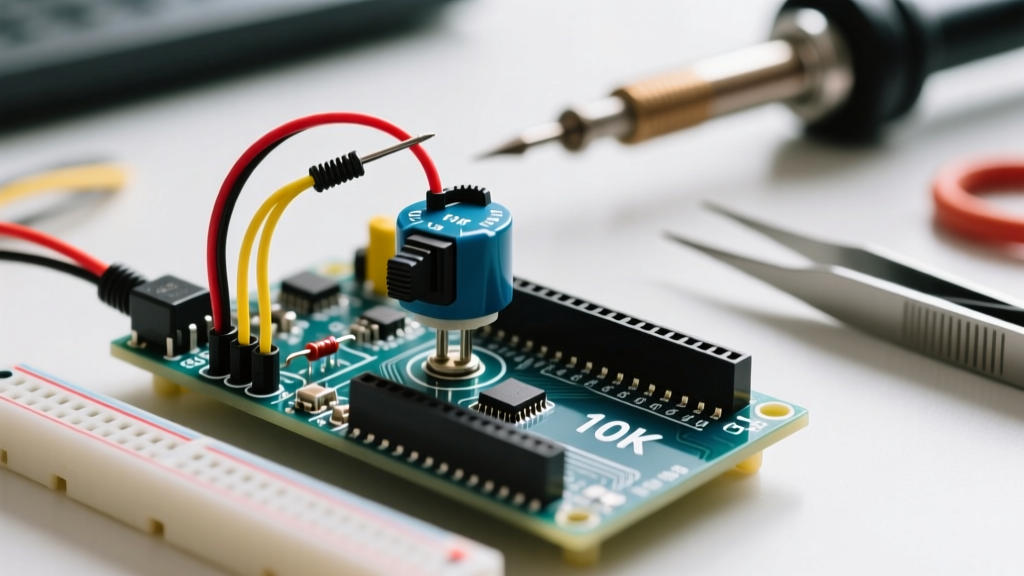
A potentiometer used for analog input is wired as a voltage divider, not as a variable resistor (rheostat). You must use all three terminals. For a comprehensive breakdown of the underlying physics, the SparkFun Voltage Divider Tutorial provides an excellent foundational overview.
| Potentiometer Pin | Electrical Role | Arduino Connection | Wire Color (Standard) |
|---|---|---|---|
| Pin 1 (CCW) | Reference High | 5V (or 3.3V) | Red |
| Pin 2 (Wiper) | Variable Output | Analog Pin (e.g., A0) | Yellow / Signal |
| Pin 3 (CW) | Reference Low | GND | Black |
Note on Pin 1 and Pin 3: Electrically, swapping Pin 1 and Pin 3 will not damage the circuit. However, it will reverse the logical direction of the knob. If turning the knob clockwise decreases your serial monitor values, simply swap the 5V and GND wires on the outer legs.
Translating Voltage to Code: ADC Mapping
When the wiper moves, it alters the ratio of resistance between the top and bottom halves of the carbon track, outputting a voltage between 0V and 5V. The Arduino's analogRead() function measures this voltage and maps it to a 10-bit integer (0 to 1023).
Each step of the 10-bit ADC represents approximately 4.88 millivolts (5.0V / 1023). To convert the raw ADC reading back into a usable voltage or a specific parameter range, use the following logic:
// Read the raw 10-bit value from the 10K pot
int rawValue = analogRead(A0);

// Convert to actual voltage (0.0 to 5.0V)
float voltage = rawValue * (5.0 / 1023.0);

// Map the raw value to a custom range (e.g., PWM duty cycle 0-255)
int pwmOutput = map(rawValue, 0, 1023, 0, 255);
Real-World Failure Modes & Signal Noise
In theoretical schematics, a 10K pot outputs a perfectly smooth voltage. In physical reality, carbon-track potentiometers are mechanical devices prone to noise, wiper bounce, and environmental interference. If your serial monitor shows the value jumping between 510, 514, and 508 while the knob is sitting still, you are experiencing wiper noise.
Hardware Fix: The RC Low-Pass Filter
The most robust way to eliminate high-frequency noise is to add a hardware RC (Resistor-Capacitor) low-pass filter. By soldering a 100nF (0.1µF) ceramic capacitor directly between the Wiper (Pin 2) and GND (Pin 3), you create a filter that smooths out micro-fluctuations.
Let us calculate the cutoff frequency ($f_c$) of this filter. When the pot is at the 50% midpoint, the Thevenin equivalent resistance ($R_{th}$) looking out from the wiper is the parallel combination of the two 5K halves: $5K || 5K = 2.5K\Omega$.
- $R = 2,500 \Omega$
- $C = 0.0000001 F$ (100nF)
- $f_c = \frac{1}{2 \pi R C} \approx 636 Hz$
This 636 Hz cutoff frequency is perfect. It effortlessly blocks high-frequency electrical noise and mechanical wiper scratch (which occurs in the kHz range) while remaining entirely transparent to human hand movements (which occur below 5 Hz).
Software Fix: Exponential Moving Average (EMA)
If you cannot modify the hardware, you must implement software debouncing. A simple arithmetic mean can introduce lag, making the UI feel unresponsive. Instead, use an Exponential Moving Average (EMA) to smooth the analogRead() data dynamically:
float smoothedValue = 0;
const float alpha = 0.1; // Lower = smoother but more lag

void loop() {
  int raw = analogRead(A0);
  smoothedValue = (alpha * raw) + ((1.0 - alpha) * smoothedValue);
  // Use smoothedValue for your logic
}
Summary of Best Practices
To guarantee flawless analog readings in your microcontroller projects, always source B10K (Linear) potentiometers. Ensure your wiring utilizes the full three-terminal voltage divider topology, and respect the microcontroller's 10KΩ source impedance limit to allow the internal sample-and-hold capacitor to charge accurately. Finally, pair your hardware with a 100nF bypass capacitor on the wiper pin to eliminate the mechanical noise inherent in carbon-track components.