
When working with an ESP32 dev kit, few things are as frustrating as a sudden barrage of red text in the Arduino IDE. Unlike the forgiving architecture of an ATmega328P-based Arduino Uno, the ESP32-WROOM-32 module operates on tight timing margins, complex dual-core boot sequences, and strict power delivery requirements. Generic advice like "reinstall your CH340 drivers" rarely solves deep-rooted hardware and timing faults.
This diagnostic guide bypasses the basics and dives into the electrical and architectural realities of ESP32 error diagnosis. We will dissect auto-reset circuit failures, AMS1117-3.3 voltage regulator limits, strapping pin conflicts, and FreeRTOS watchdog panics to get your microcontroller back online.
The Anatomy of an ESP32 Dev Kit Upload Failure
The most ubiquitous error encountered by makers is the Failed to connect to ESP32: Timed out waiting for packet header message. This is fundamentally a handshake failure between your PC's USB-UART bridge and the ESP32's ROM bootloader.
USB-UART Bridge Timing and the EN Pin Capacitor
Most generic ESP32 dev kits utilize either a CH340G or CP2102 USB-to-serial chip. To enter the bootloader automatically, the IDE pulses the DTR and RTS lines to toggle the EN (Enable) and GPIO0 pins. The hardware implementation relies on a specific RC delay circuit—usually a 10k resistor and a 1µF capacitor on the EN pin.
Expert Insight: If the capacitor on the EN line is too large (e.g., 10µF on some poorly cloned boards), the discharge time exceeds the Arduino IDE's strict bootloader timeout window. The ESP32 resets, but misses the GPIO0 bootloader strapping signal, resulting in a standard boot instead of an upload-ready state.
The Hardware Fix: If you suspect an EN pin timing issue, bypass the auto-reset by using the manual "BOOT button dance." Hold the BOOT button (GPIO0 Low), press and release the EN button, then release the BOOT button exactly when the IDE console reads Connecting....
Power Delivery Faults: Brownouts and LDO Limits
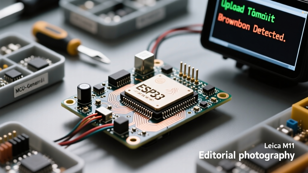
If your serial monitor spits out Brownout detector was triggered immediately upon boot or when initializing Wi-Fi, your power delivery network (PDN) is failing under transient loads.
The AMS1117-3.3 Thermal and Current Bottleneck
Standard ESP32 dev kits regulate 5V USB down to 3.3V using an AMS1117-3.3 Linear Dropout (LDO) regulator. While the datasheet claims an 800mA output, the AMS1117 is highly susceptible to thermal throttling and requires a minimum input of 4.5V to maintain regulation. When the ESP32's Wi-Fi radio transmits, it creates current spikes up to 500mA. If your USB cable has high resistance, the 5V input drops below 4.5V, the LDO drops out, and the ESP32's internal brownout detector (set at ~2.4V) triggers a hardware reset.
| Cable Quality | Wire Gauge (AWG) | Resistance (1m) | Voltage Drop @ 500mA | Dev Kit Behavior |
|---|---|---|---|---|
| Premium Silicone | 22 AWG | 0.05 Ω | 0.05 V | Stable Boot & TX |
| Standard PVC | 26 AWG | 0.13 Ω | 0.13 V | Stable (Marginal) |
| Cheap / Thin Cable | 30 AWG | 0.34 Ω | 0.34 V | Boot Loop / Brownout |
The Hardware Fix: Solder a 470µF low-ESR electrolytic capacitor directly across the 5V and GND pins on the dev kit header to supply transient Wi-Fi TX current. Alternatively, bypass the onboard LDO entirely by feeding a clean 3.3V source (capable of 1A+) directly into the 3V3 pin.
Decoding Serial Monitor Garbage and Baud Rates
Seeing strings of ÿÿÿ or ets Jan 8 2013,rst cause:2, boot mode:(3,6) is not a sign of a broken chip; it is a baud rate mismatch between the ESP32's ROM bootloader and your serial monitor.
The ESP32 ROM bootloader outputs diagnostic data at 74880 baud (a byproduct of the 40MHz crystal divider). However, the Arduino core defaults to 115200 baud for the Serial.begin() application layer. If you open the Serial Monitor at 115200 while the chip is stuck in a boot loop (never reaching your setup() function), you will only see the garbled 74880 ROM output.
- Diagnostic Step: Switch your Serial Monitor to exactly 74880 baud.
- Interpretation: If you see
rst cause:4, it indicates a hardware watchdog reset. If you seeflash read err, 1000, the SPI flash memory is corrupted or the GPIO strapping pins are misconfigured.
Strapping Pin Conflicts: The Silent Boot Killer
The ESP32 samples specific GPIO pins during the EN rising edge to determine boot modes and flash voltages. Wiring sensors to these pins on your ESP32 dev kit without understanding the consequences will lead to silent boot failures or core panics. According to the Espressif ESP32 Datasheet, the following pins are critical:
| Strapping Pin | Default State | Impact if Altered at Boot |
|---|---|---|
| GPIO0 | High (Pull-up) | Pulled Low: Enters UART Bootloader (prevents normal execution). |
| GPIO2 | Low | Pulled High: Blocks boot entirely. Must be low or floating for flash boot. |
| GPIO12 | Low | Pulled High: Switches internal flash voltage regulator to 1.8V. Causes immediate panic on 3.3V flash chips. |
| GPIO15 | Low | Pulled High: Enables verbose debug serial output from the bootloader. |
Real-World Scenario: A common mistake is wiring a relay module or an active-high sensor to GPIO12. Upon reset, the sensor pulls GPIO12 high. The ESP32 reads this, assumes a 1.8V SPI flash is attached, and lowers the internal VDD_SIO voltage. The 3.3V flash chip brownouts, resulting in a Guru Meditation Error: Core 1 panic'ed (Cache disabled but cached memory region accessed). Always consult the Espressif Hardware Design Guidelines before assigning pins.
Resolving Core Panics and FreeRTOS Watchdogs
The ESP32 runs FreeRTOS under the hood. The Arduino ESP32 Core Repository abstracts this, but poor sketch management will trigger the Task Watchdog Timer (TWDT).
The Interrupt WDT Timeout
If your serial monitor outputs Guru Meditation Error: Core 1 panic'ed (Interrupt wdt timeout on CPU1), your code is starving the FreeRTOS idle task. This typically happens when:
- You use
delay()inside an Interrupt Service Routine (ISR). - You execute blocking I2C or SPI polling loops without yielding to the OS.
- Wi-Fi/BT stack events on Core 0 are blocked by heavy user-code processing.
The Software Fix: Never use blocking functions inside an ISR. Flag a volatile boolean variable in the ISR, and handle the heavy lifting in the loop(). If you must run a long, tight polling loop, insert yield(); or delay(1); to feed the watchdog and allow background RF tasks to execute.
IRAM_ATTR and Memory Allocation
When attaching interrupts via attachInterrupt(), the function must reside in the Instruction RAM (IRAM) for fast execution. Failing to tag the function results in a Cache disabled panic if the interrupt fires while the flash cache is temporarily disabled (e.g., during OTA updates or SPI flash writes).
void IRAM_ATTR handleMotion() {
  // Keep this extremely brief
  motionDetected = true;
}
Summary Diagnostic Checklist
Before blaming a defective ESP32 dev kit, systematically verify the physical layer. Swap to a verified 22-AWG data cable, measure the 5V and 3.3V rails with a multimeter during a Wi-Fi TX burst, ensure GPIO12 is not tied to a 5V logic source, and confirm your Serial Monitor is set to 74880 baud to read ROM bootloader panic codes. Mastering these hardware-software boundary conditions is what separates a novice maker from an embedded systems engineer.