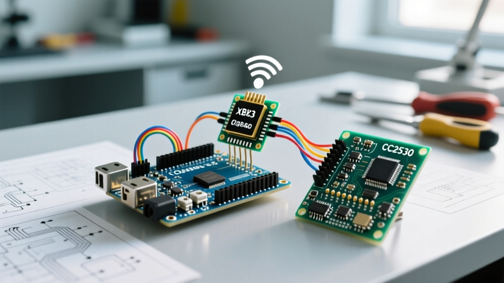

Serial communication is the undisputed backbone of microcontroller debugging and inter-device networking. Yet, if you spend more than five minutes on the Arduino forums or the r/arduino subreddit, you will inevitably encounter the same frustrated posts: 'My serial monitor is printing gibberish,' or 'My ESP32 keeps resetting when I connect the sensor.' More often than not, the culprit is not a flawed sketch, but a fundamental misunderstanding of how UART pins operate in real-world, non-ideal conditions.
This guide synthesizes years of crowdsourced troubleshooting, post-mortem analyses, and workbench wisdom from the maker community. We are moving past the basic 'TX to RX' tutorials to explore the electrical realities, voltage domain clashes, and timing anomalies that actually cause UART failures in the wild.
The Maker's Dilemma: Why UART Pins Fail in the Wild
The Universal Asynchronous Receiver-Transmitter (UART) protocol is elegantly simple because it lacks a dedicated clock line. However, this simplicity is also its greatest vulnerability. Without a clock to synchronize the sender and receiver, both devices must rely on pre-agreed timing (baud rate) and a shared electrical reference. When community members report intermittent data corruption that only happens when a motor spins or when the device is enclosed in a metal case, the issue almost always traces back to signal integrity and ground referencing on the UART pins.
'The most common mistake I see in beginner projects isn't swapping TX and RX; it is assuming the USB cable's ground is sufficient for a multi-device serial bus. Always run a dedicated ground wire alongside your UART pairs.' — EmbeddedVeteran, Arduino Forum Moderator
Decoding the Hardware: TX, RX, and the Ground Truth
At the physical layer, UART requires a minimum of three connections for reliable operation: Transmit (TX), Receive (RX), and Ground (GND). The community golden rule is TX connects to RX, and RX connects to TX. However, the ground connection is frequently treated as an afterthought.
The Ground Loop and Common Mode Noise
When you connect an Arduino Uno to a GPS module via UART pins, the return current for the serial signals must flow back to the originating microcontroller. If you rely on long, thin jumper wires for the ground connection, you introduce parasitic inductance. When the TX pin transitions from LOW to HIGH, the sudden current spike creates a voltage differential across the ground wire. If this differential exceeds the logic threshold of the receiving RX pin, the microcontroller reads a false bit, resulting in a corrupted byte. The community consensus is strict: for any UART run longer than 15 centimeters, use a twisted pair cable where one wire is TX, one is RX, and a third, equally thick wire is GND.
Voltage Domain Clashes: 5V vs 3.3V Community Disasters
Perhaps the most destructive mistake documented in maker communities is directly connecting 5V UART pins to 3.3V microcontrollers. Connecting the TX pin of a 5V Arduino Uno directly to the RX pin of a 3.3V ESP32 or Raspberry Pi Pico is a recipe for silicon death.
Understanding Absolute Maximum Ratings
According to the Arduino UART Documentation and various silicon datasheets, the absolute maximum voltage on any I/O pin is typically VDD + 0.3V. For a 3.3V ESP32, feeding it 5V from an ATmega328P forces current through the internal ESD protection diodes. Over time, this causes electromigration, leading to increased leakage current, erratic behavior, and eventually a dead microcontroller.
Level Shifting Solutions That Actually Work
The community has tested dozens of level-shifting methods. Here is the hierarchy of reliability:
- The BSS138 MOSFET Bi-Directional Shifter: The gold standard for I2C and low-speed UART. Boards utilizing the BSS138 N-channel MOSFET (like the SparkFun BOB-12009) safely translate 5V to 3.3V without the propagation delay issues of older chips. However, at baud rates above 115200, the parasitic capacitance of the MOSFET gate can round off the square waves, causing bit errors.
- The CD4050BE Unidirectional Buffer: For high-speed UART (up to 1Mbps), community experts recommend the CD4050BE hex buffer. By powering the CD4050BE at 3.3V, it naturally clamps the 5V Arduino TX signal down to a safe 3.3V logic HIGH for the ESP32 RX pin. Because it is unidirectional, you must use two chips (or carefully route the remaining channels) if you need bi-directional communication.
- The Resistor Divider: Using a 2kΩ and 3.3kΩ resistor divider on the TX line is a frequent 'quick fix' suggested on forums. While it works for 9600 baud, the RC time constant created by the resistors and the stray capacitance of the breadboard will completely destroy signal integrity at 115200 baud. Avoid this for production or high-speed applications.
Crowdsourced Baud Rate and Timing Anomalies
'Why does 115200 baud work on my Uno, but fail on my standalone ATmega328P running on the internal 8MHz oscillator?' This is a classic forum query. The answer lies in the math of the UART baud rate generator.
The AVR microcontroller calculates the baud rate by dividing the system clock. Because the divisors are integers, fractional remainders result in timing errors. According to the Espressif UART Technical Reference, modern SoCs like the ESP32 use fractional dividers, resulting in near-zero baud rate error. The ATmega328P, however, relies on integer division.
At 16MHz, attempting to generate 115200 baud results in a -3.5% error. Most UART receivers can tolerate up to a ±4% mismatch. However, if you switch to the internal 8MHz RC oscillator, the error at 115200 baud balloons to over 7%, guaranteeing frame errors. The community workaround is to enable the U2X (Double Speed) bit in the AVR USART control register, which changes the divisor multiplier and reduces the 16MHz error to a highly stable +2.1%.
Microcontroller UART Pin Mapping Matrix
To save you from digging through schematics, the community has compiled this definitive mapping matrix for the most popular development boards. Always verify these against your specific board revision, as clone manufacturers occasionally reroute pins.
| Microcontroller Board | Hardware UART0 (USB/Default) | Hardware UART1 / UART2 | Logic Level | 5V Tolerant RX? |
|---|---|---|---|---|
| Arduino Uno (ATmega328P) | Pins 0 (RX), 1 (TX) | None (SoftwareSerial required) | 5V | N/A (Native 5V) |
| Arduino Mega 2560 | Pins 0 (RX), 1 (TX) | UART1: 19/18, UART2: 17/16, UART3: 15/14 | 5V | N/A (Native 5V) |
| ESP32 DevKit V1 | UART0: GPIO3 (RX), GPIO1 (TX) | UART1: GPIO9/10 (often used by flash), UART2: 16/17 | 3.3V | No (Max 3.6V) |
| Raspberry Pi Pico (RP2040) | UART0: GP1 (TX), GP0 (RX) (Default mapping) | UART1: GP4 (TX), GP5 (RX) (Default mapping) | 3.3V | No (Max 3.6V) |
Forum Favorites: SoftwareSerial vs Hardware UART
When a maker runs out of hardware UART pins, the immediate reflex is to include the SoftwareSerial.h library. While this library is a marvel of software engineering, the community strongly advises understanding its severe limitations before deploying it in a complex project.
The Interrupt Blocking Problem
SoftwareSerial works by using pin-change interrupts and tight delay loops to bit-bang the serial protocol. When a SoftwareSerial port is actively receiving data, it disables global interrupts to maintain the microsecond-level timing required to sample the incoming bits. If your project also relies on I2C sensors, SPI displays, or servo motors, receiving a single byte over SoftwareSerial will cause your I2C bus to hang or your servos to jitter violently. Furthermore, SoftwareSerial cannot transmit and receive simultaneously, and it reliably maxes out at 57600 baud on a 16MHz AVR.
When to Ditch SoftwareSerial
If you are using an ESP32 or a Raspberry Pi Pico, never use software serial emulation. The ESP32 features a highly flexible UART matrix that allows you to map UART1 or UART2 to almost any available GPIO pin via the hardware IO MUX. On the RP2040, the Programmable I/O (PIO) state machines can handle UART protocols in the background without touching the main CPU cores or blocking interrupts. Reserve SoftwareSerial exclusively for simple, low-speed (9600 baud) debugging on legacy 8-bit AVR chips where no other timing-critical peripherals are in use.
Final Takeaways from the Workbench
Mastering UART pins requires looking past the IDE's Serial.begin() command and respecting the physical layer. Always provide a robust, low-impedance common ground. Never trust a 5V signal to enter a 3.3V RX pin without a proper level shifter like the BSS138 or CD4050BE. Finally, respect the mathematical limitations of your microcontroller's baud rate generator and avoid software emulation whenever hardware peripherals are available. By applying these community-vetted principles, you will eliminate the vast majority of serial communication gremlins from your electronics workbench.