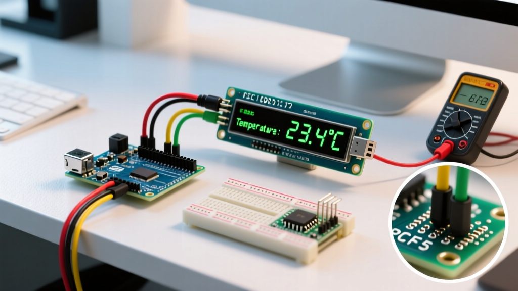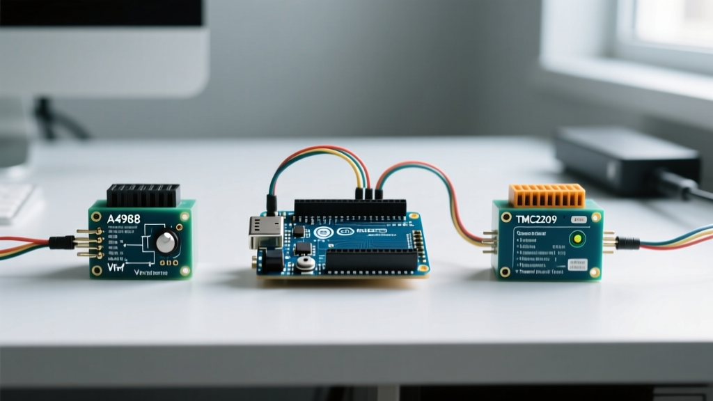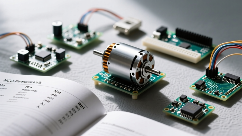

When sourcing a stepper motor for Arduino projects, most hobbyists simply search for 'NEMA 17' and click buy on the first result. While NEMA 17 defines the physical mounting dimensions (42.3mm x 42.3mm), it tells you absolutely nothing about the electrical characteristics, torque curves, or speed limitations of the motor inside. To build reliable CNC routers, 3D printers, or precision pan-tilt camera rigs, you must learn to read the manufacturer's datasheet. This guide translates dense electromechanical specifications into actionable insights for microcontroller integration.
The Anatomy of a Stepper Motor Datasheet
A typical stepper motor datasheet from manufacturers like Moons, LDO, or OmniStepper is divided into mechanical and electrical specifications. For Arduino integration, the mechanical specs (like rotor inertia and weight) dictate your acceleration limits, while the electrical specs (resistance, inductance, and rated current) dictate your choice of motor driver and power supply. Ignoring the electrical section is the number one reason DIY builds suffer from missed steps, overheated drivers, and stalled motors at high speeds.
The Great Voltage Myth: Rated Voltage vs. Drive Voltage
The most misunderstood line on any stepper motor datasheet is the 'Rated Voltage.' You will often see a NEMA 17 motor with a rated voltage of 3.2V or 4.2V. Beginners frequently assume they must power the motor with a 4.2V power supply. This is a critical mistake.
The Datasheet Translation: The 'Rated Voltage' on a datasheet is simply the voltage required to push the 'Rated Current' through the motor coils while the motor is stationary, calculated via Ohm's Law (V = I × R). It is not the voltage you should use to drive the motor in a real-world application.
When selecting a stepper motor for Arduino, you will use a chopper stepper driver (like the A4988, DRV8825, or TMC2209). These drivers use high-frequency PWM to regulate current. By supplying a much higher voltage (typically 12V to 24V) to the driver, you force current through the motor's inductive coils much faster. This overcomes the inductance lag, allowing the motor to maintain high torque at high RPMs. If you only supply the 'rated voltage,' your motor will lose almost all its torque after just a few hundred RPM.
Inductance: The Hidden Speed Killer
Phase Inductance (measured in millihenries, mH) is the most vital spec for determining a motor's top speed. Inductance resists changes in current. When your Arduino commands the motor to step rapidly, the driver must reverse the current direction in the coils instantly. High inductance prevents the current from reaching the target level before the next step is commanded, resulting in a severe drop in dynamic torque.
Calculating the Inductance Limit
As a general rule of thumb derived from motor physics, the maximum usable RPM before torque drops off a cliff can be estimated by the formula:
Max RPM ≈ (Supply Voltage × 1000) / (Phase Inductance × Rated Current)
If you are building a high-speed pick-and-place machine, you need a low-inductance motor (under 2.0 mH). If you are building a high-torque, low-speed camera slider, a high-inductance motor (6.0+ mH) is perfectly acceptable and often cheaper.
Datasheet Showdown: Three Common NEMA 17 Motors
To illustrate how datasheet specs dictate real-world performance, let us compare three popular NEMA 17 models frequently used in the maker community.
| Specification | 17HS4401 (Standard) | 42BYGHM810 (High Torque) | 17HS19-2004S (High Speed) |
|---|---|---|---|
| Phase Current | 1.5 A | 1.7 A | 2.0 A |
| Phase Resistance | 2.8 Ω | 2.2 Ω | 1.1 Ω |
| Phase Inductance | 3.2 mH | 8.0 mH | 1.6 mH |
| Holding Torque | 40 Ncm (56 oz-in) | 55 Ncm (78 oz-in) | 59 Ncm (83 oz-in) |
| Rotor Inertia | 54 g·cm² | 80 g·cm² | 80 g·cm² |
| Best Application | General 3D Printing | Heavy Load Extruders | CNC Routers / Laser |
Analysis: The 42BYGHM810 boasts massive holding torque, but its 8.0 mH inductance means it will stall at high speeds unless driven by a 36V+ power supply. Conversely, the 17HS19-2004S has very low inductance (1.6 mH), allowing it to spin at high RPMs on a standard 24V supply without losing torque, making it the superior choice for CNC applications where rapid traverse rates are required.
Matching the Motor to the Driver
Once you have extracted the 'Rated Current' from the datasheet, you must select an Arduino-compatible driver capable of handling that continuous current without thermal shutdown. According to the Pololu A4988 carrier documentation, the A4988 can deliver 1A per phase without cooling, and up to 2A with active airflow. However, the Texas Instruments DRV8825 datasheet reveals a higher thermal threshold, supporting up to 2.5A with adequate heatsinking.
Setting the Current Limit (Vref)
You must configure the driver's current limit to match the datasheet's Phase Current. Running a 1.5A motor at 2.0A will not give you more torque; it will only saturate the magnetic core and generate excess heat. Use a multimeter to measure the Vref pin on your driver:
- A4988 Formula: Vref = Rated Current × 8 × Rsense (e.g., 1.5A × 8 × 0.05Ω = 0.6V)
- DRV8825 Formula: Vref = Rated Current × 5 × Rsense (e.g., 1.5A × 5 × 0.1Ω = 0.75V)
For ultra-quiet operation in audio-visual peripherals, consider the Trinamic TMC2209, which uses StealthChop2 technology to eliminate the whining noise associated with traditional chopper drivers, though it is best suited for motors with inductance above 2.0 mH.
Real-World Failure Modes and Datasheet Red Flags
Even with the correct wiring, ignoring specific datasheet parameters leads to distinct failure modes in Arduino-driven systems:
1. Mid-Band Resonance
Stepper motors suffer from a phenomenon called mid-band resonance, typically occurring between 10,000 and 20,000 microsteps per second. The motor will violently vibrate and stall. Datasheets rarely plot this, but you can mitigate it by enabling 1/16 or 1/32 microstepping on your driver, or by using mechanical dampers on the rear shaft.
2. Inertia Mismatch
The datasheet lists 'Rotor Inertia.' If the load you are moving (via a lead screw or belt) has an inertia more than 10 times greater than the rotor inertia, the motor will overshoot or miss steps during acceleration. You must use your Arduino code (via libraries like AccelStepper) to implement strict trapezoidal or S-curve acceleration profiles to respect the motor's physical limits.
3. Thermal Runaway
If your datasheet specifies a 'Temperature Rise' of 80°C at rated current, this means the motor casing will reach 80°C above ambient temperature when stationary and fully energized. This is normal for Class B insulation (rated to 130°C). However, if you are mounting the motor to a 3D-printed PLA bracket, the radiant heat will soften your mount. Always disable the motor enable pin via your Arduino when the system is idle to prevent structural failure.
Final Integration Checklist
Before writing your Arduino sketch, verify these three datasheet points:
- Step Angle: Confirm if the motor is 1.8° (200 steps/rev) or 0.9° (400 steps/rev). This directly impacts your steps-per-mm calculations in firmware.
- Wire Color Code: Never trust standard wire colors. Use a multimeter to find the two coil pairs (A and B) by checking for continuity, then reference the datasheet's specific winding diagram to ensure correct bipolar phasing.
- Power Supply Sizing: A single 1.5A NEMA 17 motor driven at 12V will draw roughly 1A from the power supply (due to driver efficiency and chopping). Multiply this by the number of motors in your array to size your 12V/24V DC supply correctly.
By treating the datasheet as an integration manual rather than a mere spec sheet, you elevate your Arduino projects from unreliable prototypes to robust, industrial-grade electromechanical systems. For further reading on microcontroller motor control, review the comprehensive guides available via the Adafruit Learning System.