
Why I2C is the 2026 Standard for 16x2 LCDs
When learning microcontroller interfacing, displaying sensor data is a critical milestone. While parallel 16x2 LCDs (based on the Hitachi HD44780U controller) historically required 6 digital pins and a clumsy 10kΩ contrast potentiometer, the modern standard relies on I2C adapter backpacks. By using an I2C expander chip, you reduce the wiring to just four pins (VCC, GND, SDA, SCL) and free up valuable GPIO pins for sensors and motors.
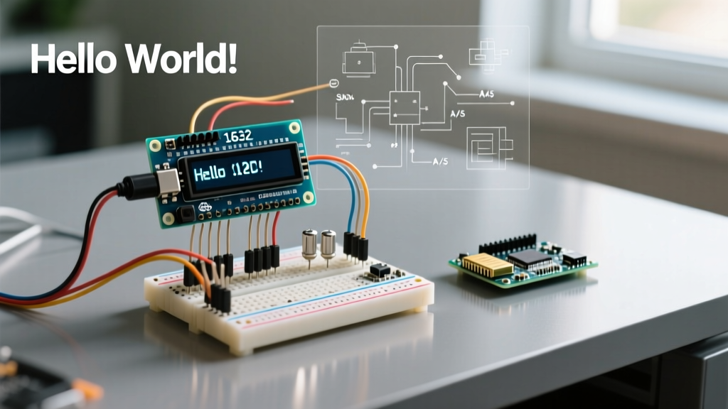
In this beginner interfacing tutorial, we will walk through the exact lcd arduino code required to initialize, write to, and customize a 16x2 I2C display. We will also cover hardware selection, I2C address conflicts, and memory management techniques essential for robust embedded projects.
Hardware Bill of Materials (BOM)
Before writing code, ensure you have the correct hardware. As of 2026, the Arduino Uno R4 Minima is the recommended baseline board due to its 32-bit Arm Cortex-M4 processor and dedicated I2C pins, though this code remains fully backward-compatible with the classic Uno R3.
| Component | Specific Model / Part Number | Approx. Price (2026) | Notes |
|---|---|---|---|
| Microcontroller | Arduino Uno R4 Minima | $27.50 | Features dedicated SDA/SCL headers near AREF. |
| Display Module | 16x2 LCD with I2C Backpack (HD44780) | $5.50 - $7.00 | Ensure it has the PCF8574 or PCF8574A expander chip. |
| Wiring | F/M Dupont Jumper Wires (20cm) | $4.00 | Minimum 4 wires required for I2C. |
Wiring the I2C Backpack to Arduino
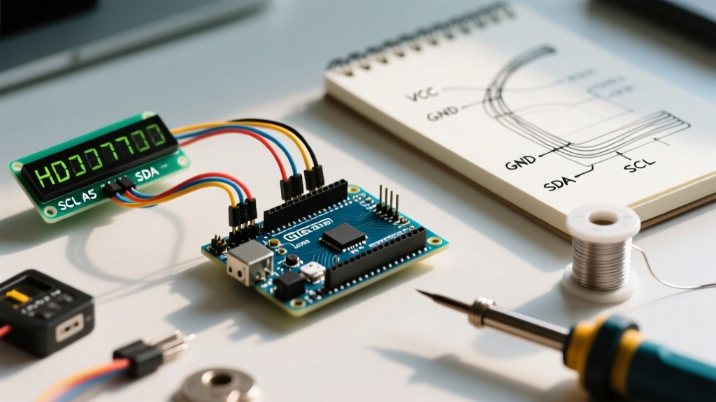
The I2C protocol uses a shared bus, meaning you only need to connect four pins. If you are using the newer Arduino Uno R4, utilize the dedicated I2C pins rather than the analog pins used on older boards.
- VCC → 5V pin (Do not use 3.3V; the HD44780 logic requires 4.5V to 5.5V for stable backlight and contrast).
- GND → GND pin.
- SDA → SDA pin (On Uno R3, this is A4; on Uno R4, use the dedicated SDA header).
- SCL → SCL pin (On Uno R3, this is A5; on Uno R4, use the dedicated SCL header).
Step 1: Finding Your I2C Address (The 0x27 vs 0x3F Trap)
The most common point of failure for beginners writing lcd arduino code is hardcoding the wrong I2C address. I2C backpacks typically use the NXP PCF8574 I/O expander. Depending on the exact silicon variant soldered onto the backpack, the base address shifts:
- PCF8574T chip: Default address is usually
0x27. - PCF8574AT chip: Default address is usually
0x3F.
Before writing your display code, upload an I2C Scanner sketch (available via the Arduino IDE Examples menu) to verify your exact address. For this tutorial, we will assume the standard 0x27 address.
Step 2: The Core LCD Arduino Code
To interface with the I2C backpack, you must install the LiquidCrystal_I2C library by Frank de Brabander via the Arduino Library Manager (Sketch > Include Library > Manage Libraries). Do not confuse this with the default parallel LiquidCrystal library.
#include <Wire.h>
#include <LiquidCrystal_I2C.h>

// Initialize the library with the I2C address, columns, and rows
// Address 0x27, 16 columns, 2 rows
LiquidCrystal_I2C lcd(0x27, 16, 2);

void setup() {
  // Initialize the LCD and turn on the backlight
  lcd.init();
  lcd.backlight();

  // Print a static startup message
  lcd.setCursor(0, 0); // Column 0, Row 0 (Top Left)
  lcd.print("ElectricalFlux");

  lcd.setCursor(0, 1); // Column 0, Row 1 (Bottom Left)
  lcd.print("Booting System..");

  delay(2000);
  lcd.clear();
}

void loop() {
  // Display dynamic sensor data (simulated here)
  float temperature = 23.45;
  int humidity = 58;

  lcd.setCursor(0, 0);
  // Use the F() macro to save SRAM (explained below)
  lcd.print(F("Temp: "));
  lcd.print(temperature, 1); // Print with 1 decimal place
  lcd.print((char)223);      // Degree symbol
  lcd.print("C   ");         // Padding to clear old characters

  lcd.setCursor(0, 1);
  lcd.print(F("Hum: "));
  lcd.print(humidity);
  lcd.print("%     ");

  delay(1000);
}
Deep Dive: Code Architecture & Memory Management
Writing efficient lcd arduino code goes beyond simply printing strings. Microcontrollers like the Uno R3 have only 2KB of SRAM. Every string literal you pass to lcd.print() consumes precious RAM.
The F() Macro for SRAM Preservation
In the code above, notice the use of the F() macro: lcd.print(F("Temp: "));. This instructs the compiler to store the string in Flash memory (PROGMEM) rather than copying it into SRAM at runtime. According to the official Arduino LiquidCrystal documentation, utilizing Flash storage for static UI text prevents memory fragmentation and prevents the microcontroller from crashing in complex projects involving multiple sensors and Wi-Fi buffers.
Handling Ghosting and Overwrite Artifacts
When updating dynamic data (like a temperature reading dropping from 100.0 to 99.9), the LCD will leave trailing artifacts if you don't clear the previous characters. Notice the trailing spaces in lcd.print("C "); in the code block above. This manual padding technique is vastly more efficient than calling lcd.clear() inside the loop(), which causes a visible, annoying screen flicker at high refresh rates.
Step 3: Designing Custom Characters
The HD44780U controller includes a CGRAM (Character Generator RAM) that allows you to define up to 8 custom characters. Each character is a 5x8 pixel grid, mapped using an array of 8 bytes where the lower 5 bits represent the pixels (1 for ON, 0 for OFF).
// Define a custom 'Battery' icon
byte battery[8] = {
  0b01110,
  0b11111,
  0b10001,
  0b11111,
  0b11111,
  0b11111,
  0b11111,
  0b11111
};

void setup() {
  lcd.init();
  lcd.backlight();

  // Create a new character at index 0
  lcd.createChar(0, battery);

  lcd.setCursor(0, 0);
  lcd.write(0); // Print the custom character
  lcd.print(" Battery: 85%");
}
Troubleshooting Common Failure Modes
Even with perfect code, hardware quirks can derail your project. Use this diagnostic matrix to resolve common 16x2 LCD issues.
⚠️ Symptom: Screen is completely blank (No backlight, no text).
Diagnosis: Power delivery failure. Ensure you are connected to the 5V pin, not the 3.3V pin. The I2C backpack requires 5V to drive the backlight LEDs and the logic level shifter. If using an ESP32 or Raspberry Pi Pico (which are 3.3V logic devices), you must use a bidirectional logic level converter on the SDA/SCL lines to safely interface with the 5V LCD.
⚠️ Symptom: Backlight is ON, but only solid black boxes appear on the top row.
Diagnosis: Contrast misalignment or I2C handshake failure. First, locate the small blue trim-potentiometer on the back of the I2C backpack. Use a small Phillips screwdriver to turn it counter-clockwise until the black boxes fade and text appears. If the boxes remain, your I2C address in the code (0x27) does not match the hardware. Rerun the I2C scanner.
⚠️ Symptom: Text is garbled, shifted, or scrolling randomly.
Diagnosis: I2C bus noise or missing pull-up resistors. The SparkFun I2C Tutorial notes that I2C requires pull-up resistors on SDA and SCL. While most I2C backpacks include 4.7kΩ onboard pull-ups, long wire runs (over 30cm) will introduce capacitance and corrupt the data packets. Keep I2C wires under 20cm, or add external 4.7kΩ pull-up resistors to the 5V line.
Next Steps for Peripheral Integration
Once you have mastered this foundational lcd arduino code, you can expand your system. Try integrating a DHT22 temperature sensor to feed real environmental data into the display loop, or use a rotary encoder to build a functional settings menu. The 16x2 I2C LCD remains one of the most reliable, cost-effective debugging and telemetry tools in the electronics workbench.