
Why Reading the Datasheet Matters for Stepper Projects
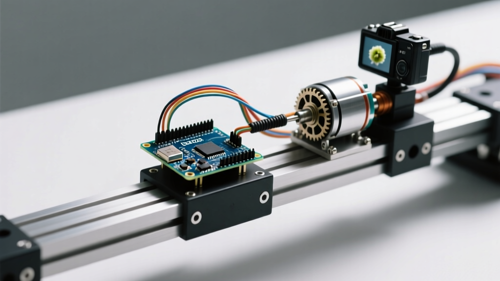
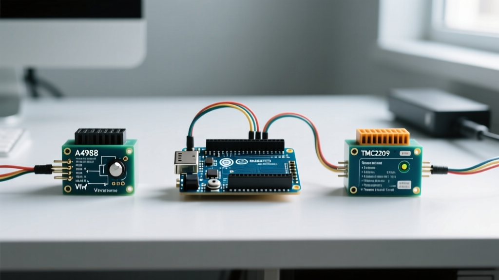
When configuring a driver stepper Arduino circuit, enthusiasts often rely on copy-paste wiring diagrams and generic tutorials. This approach inevitably leads to melted driver boards, acoustic resonance, and missed steps. To build reliable CNC routers, 3D printers, or automated camera sliders in 2026, you must understand the silicon-level behavior of your motor driver. In this datasheet explainer, we decode the critical specifications of the ubiquitous Allegro A4988 and the advanced Trinamic TMC2209, translating dense engineering tables into actionable Arduino integration strategies.
Absolute Maximum Ratings: The Inductive Kickback Trap
Every datasheet begins with the 'Absolute Maximum Ratings' table. For the Allegro A4988, the maximum supply voltage (VMOT) is listed as 35V. However, designing a 34V power supply for your Arduino stepper setup is a guaranteed way to destroy the chip.
Engineering Reality Check: Stepper motors are highly inductive loads. When the internal MOSFETs switch off, the collapsing magnetic field generates voltage spikes (inductive kickback). If your power supply sits at 34V, a 5V spike will push the VMOT pin past the 35V absolute maximum, instantly frying the driver. Always maintain a 20% safety margin. For a 35V rated driver, cap your PSU at 28V.
Real-World Voltage & Current Matrix
| Parameter | A4988 Datasheet Max | Safe Arduino Limit | TMC2209 Datasheet Max | Safe Arduino Limit |
|---|---|---|---|---|
| Logic Voltage (VDD) | 5.5V | 5.0V (Use 3.3V for ESP32) | 5.5V | 5.0V (Native 3.3V support) |
| Motor Supply (VMOT) | 35V | 28V Max | 29V | 24V Max |
| Continuous Current/Phase | 2.0A | 1.2A (w/o active cooling) | 2.0A (RMS) | 1.5A (w/ standard heatsink) |
| Typical Market Price (2026) | $2.50 - $4.00 | N/A | $9.00 - $14.00 | N/A |
Current Limiting: Decoding the Vref Math
The most common point of failure in any driver stepper Arduino build is incorrect current limiting. The datasheet provides a formula to set the reference voltage (Vref) via the onboard trimmer potentiometer. However, the formula changes based on the sense resistor (Rs) used on the PCB.
The standard Allegro formula is:
Vref = Imax * 8 * Rs
The Clone Board Sense Resistor Problem
- Genuine A4988 / High-End Clones: Often use Rs = 0.05 ohms. For a 1.5A motor, Vref = 1.5 * 8 * 0.05 = 0.6V.
- Standard Economy Clones: Frequently substitute Rs = 0.1 ohms to save costs. Using the 0.05 ohm math here will result in Vref = 1.2V, pushing 3A through a 1.5A motor and causing immediate thermal shutdown.
- Pololu Carrier Boards: Typically use Rs = 0.068 ohms or 0.11 ohms. Always visually inspect the SMD resistor marking (e.g., 'R10' means 0.1 ohms, 'R05' means 0.05 ohms) before applying power.
Step and Direction Timing Requirements
Microcontrollers execute instructions in nanoseconds, but stepper drivers require specific setup and hold times to register a step pulse. The A4988 datasheet mandates a minimum 1-microsecond pulse width. Many beginners use delayMicroseconds(1) in their Arduino sketches, which is borderline and often fails due to interrupt overhead.
According to the Trinamic TMC2209 datasheet, the minimum step pulse width is slightly more forgiving at 100 nanoseconds, but the TMC2209 introduces an internal step interpolation multiplier (up to 256 microsteps). To ensure the internal PLL locks correctly, you must feed it a base step frequency of at least 20kHz when utilizing the highest interpolation settings via UART.
Microstepping Translation Tables & Decay Modes
Microstepping divides a full 1.8-degree step into smaller increments, smoothing motion and reducing resonance. The datasheets map hardware pin states (MS1, MS2, MS3) to specific microstep resolutions.
While hardware pins allow basic microstepping configuration, the true power of the TMC2209 lies in its UART interface. By connecting the TX/RX pins to your Arduino's SoftwareSerial or hardware UART, you can dynamically alter the chopper configuration on the fly.
Decay Mode Selection: StealthChop vs. SpreadCycle
The TMC2209 introduces a critical datasheet section on decay modes that the A4988 lacks entirely:
- StealthChop2 (Voltage PWM): Operates silently at low to medium speeds. Ideal for 3D printer X/Y axes and camera sliders. Edge Case: At high accelerations, StealthChop can cause skipped steps due to delayed current regulation.
- SpreadCycle (Current Hysteresis): The default for high-torque, high-speed applications like CNC router Z-axes. It generates audible whine but provides superior positional accuracy under heavy loads.
- CoolStep & StallGuard4: Advanced features allowing the Arduino to detect motor stalls without physical limit switches by monitoring back-EMF. Requires precise UART tuning of the SGTHRS register.
Thermal Characteristics and Heatsink Sizing
Datasheets list the Junction-to-Ambient thermal resistance. For the A4988 in a standard 28-pin QFN package, this value is approximately 35 degrees Celsius per Watt.
If your Arduino code commands the driver to deliver 1.2A per phase at 12V, the internal MOSFETs will dissipate roughly 1.5W of heat as I-squared-R losses and switching losses.
The Math: 1.5W * 35C/W = 52.5C temperature rise above ambient. In a 25C room, the silicon junction hits 77.5C. While below the 165C thermal shutdown threshold, the driver will aggressively derate current as it approaches 120C, causing your stepper motor to lose holding torque mid-print. Always apply a minimum 14mm x 14mm x 4mm aluminum heatsink with thermal adhesive for continuous draws above 0.8A.
Logic Level Translation: 3.3V vs 5V Edge Cases
A frequent oversight when migrating from an Arduino Uno (5V logic) to an Arduino Nano 33 IoT or ESP32 (3.3V logic) is the logic threshold (VIH).
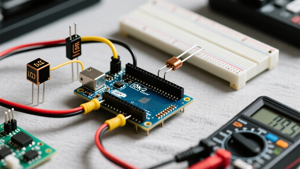
The A4988 datasheet specifies a minimum high-level input voltage of 2.0V, meaning 3.3V logic works natively. However, the TMC2209 is explicitly designed with a 3.3V to 5V tolerant I/O architecture. When wiring a driver stepper Arduino circuit on a breadboard, ensure you are not accidentally routing 5V logic into a 3.3V microcontroller's RX pin via the TMC2209's UART line, which lacks an internal pull-down resistor and can backfeed voltage, destroying the ESP32's GPIO.
Frequently Asked Questions (Datasheet Deep-Dive)
Do I need a capacitor on the VMOT pin?
Yes. The Texas Instruments DRV8825 and Allegro A4988 datasheets both mandate a decoupling capacitor (typically 100uF electrolytic) placed as close to the VMOT and GND pins as possible. This absorbs localized voltage spikes during rapid step-direction changes.
Can I hot-swap the stepper motor while the Arduino is powered?
Absolutely not. Disconnecting a stepper coil while the driver is energized causes the full supply voltage to route through the internal protection diodes to the logic ground, instantly vaporizing the driver IC. Always cut VMOT power before touching motor connectors.
Why does my motor vibrate but not spin?
This is a classic step-timing or decay-mode failure. If the Arduino is sending step pulses faster than the driver's maximum translation frequency (typically 100kHz for the A4988), the internal indexer drops steps. Lower your feed rate in firmware and verify your microstepping jumper pins are fully seated.