
The Challenge of Multi-Peripheral Arduino Setups
Building a comprehensive environmental dashboard or automated control panel rarely involves just one component. When integrating an LCD display Arduino configuration into a larger sensor array, hobbyists and engineers quickly hit the physical limitations of the microcontroller. Standard parallel LCDs consume a massive amount of digital I/O pins, leaving insufficient headroom for relays, encoders, and environmental sensors. Transitioning to an I2C-based architecture solves the pin economy problem, but it introduces complex electrical challenges—specifically bus capacitance, address collisions, and pull-up resistor conflicts—that can silently corrupt data or lock up the entire system.
Parallel vs. I2C: Pin Economy Breakdown
Before wiring multiple peripherals, it is critical to understand the pin overhead of your display choice. The table below illustrates why I2C is mandatory for multi-sensor builds.
| Display Type | Interface | Pins Required | Max Peripherals on Same Bus |
|---|---|---|---|
| Standard 16x2 LCD | Parallel (4-bit) | 6 Digital Pins | N/A (Direct wired) |
| 16x2 LCD w/ PCF8574 | I2C | 2 Pins (SDA/SCL) | Up to 8 (Address dependent) |
| 20x4 LCD w/ PCF8574T | I2C | 2 Pins (SDA/SCL) | Up to 8 (Address dependent) |
2026 Component Stack & Pricing
For a robust multi-peripheral test bench in 2026, we recommend moving away from legacy cloned boards and utilizing modern, officially supported hardware to ensure stable logic levels and reliable power delivery.
- Microcontroller: Arduino Uno R4 Minima (~$20.00). Features a 48MHz Arm Cortex-M4, native I2C pull-up support, and a robust 5V regulator.
- Display: 16x2 I2C LCD with PCF8574T backpack (~$4.50 - $6.00). Ensure the backpack has an adjustable contrast potentiometer and a jumper to disable the onboard backlight if power budgeting is tight.
- Primary Sensor: Adafruit BME280 I2C Breakout (~$19.50). Provides temperature, humidity, and barometric pressure without the drift issues of cheaper DHT11 alternatives.
- Secondary Peripheral: DS3231 High-Precision RTC Module (~$3.50). Essential for timestamping sensor logs directly to the LCD.
Wiring the I2C LCD Display Arduino Configuration
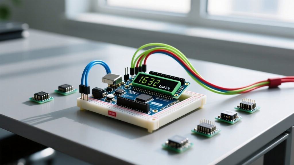
When wiring an LCD display Arduino setup alongside other I2C devices, all SDA (Serial Data) and SCL (Serial Clock) lines must be tied together in parallel. On the Arduino Uno R4, the dedicated I2C pins are A4 (SDA) and A5 (SCL).
Critical Warning: I2C Address Collisions
Many cheap PCF8574T LCD backpacks ship with the default I2C address0x27. However, some manufacturers use the PCF8574AT chip, which defaults to0x3F. Before wiring your LCD, always run an I2C scanner sketch to verify the exact hexadecimal address. If you are using multiple LCDs, you must solder the A0, A1, and A2 jumper pads on the back of the PCF8574 board to shift the addresses. Consult the Adafruit I2C Address Master List to map out your bus before applying power.
Step-by-Step Physical Routing
- Power Rails: Connect the 5V and GND pins of the Uno R4 to a dedicated breadboard power rail. Do not daisy-chain power through the sensor breakouts; the voltage drop across thin jumper wires will cause LCD backlight flickering.
- Signal Lines: Use 24 AWG stranded wire for SDA and SCL. Keep I2C traces under 30cm (12 inches) to minimize bus capacitance, which degrades the square wave signal at higher clock speeds.
- Decoupling: Place a 100nF ceramic capacitor across the VCC and GND pins directly on the LCD backpack to suppress high-frequency noise generated by the backlight inductor.
The Hidden Trap: I2C Pull-Up Resistor Math
This is where 90% of multi-peripheral LCD setups fail. The I2C bus is open-drain, meaning devices can only pull the signal line LOW. To pull the line HIGH, external pull-up resistors are required. The official NXP UM10204 I2C-bus Specification dictates strict limits on sink current and bus capacitance.
Calculating Bus Sink Current
Most I2C breakout boards (including the BME280, DS3231, and LCD backpack) include onboard 4.7kΩ pull-up resistors. When you wire them in parallel, the total resistance drops according to the formula: R_total = 1 / (1/R1 + 1/R2 + 1/R3).
If you connect an LCD, a BME280, and an RTC, you have three 4.7kΩ resistors in parallel, resulting in an equivalent resistance of roughly 1,566Ω.
According to the I2C standard, the maximum voltage for a logic LOW (VOL) is 0.4V, and the maximum sink current is 3mA for Standard Mode (100kHz). Let us calculate the actual sink current at 5V:
I = (VCC - VOL) / R_total = (5.0V - 0.4V) / 1566Ω = 2.93mA
While 2.93mA is technically under the 3mA limit, USB power from a PC often delivers 5.2V. At 5.2V, the sink current becomes 3.06mA, exceeding the specification. This causes the logic LOW to fail to reach 0.4V, resulting in the Arduino misreading bits, the LCD displaying garbage characters (black boxes), or the entire bus locking up.
The Solution: Resistor Pruning
To fix this, use a hobby knife or desoldering iron to remove the pull-up resistors from the sensor breakouts, leaving only the pull-ups on the LCD backpack and the internal pull-ups of the Arduino Uno R4 active. Alternatively, wire a dedicated 4.7kΩ resistor pair to the main power rail and disable all onboard breakout resistors.
Non-Blocking Firmware Integration
When driving an LCD display Arduino setup alongside environmental sensors, you must avoid using delay(). Reading a BME280 sensor can take up to 500ms for high-accuracy oversampling. If you block the main loop, button inputs or rotary encoders will become unresponsive. Use the Arduino Wire Library in conjunction with millis() for non-blocking execution.
#include <Wire.h>
#include <LiquidCrystal_I2C.h>
#include <Adafruit_BME280.h>

// Initialize LCD at I2C address 0x27, 16 columns, 2 rows
LiquidCrystal_I2C lcd(0x27, 16, 2);
Adafruit_BME280 bme;

unsigned long previousMillis = 0;
const long interval = 2000; // Update display every 2 seconds

void setup() {
  Wire.begin();
  lcd.init();
  lcd.backlight();
  lcd.setCursor(0, 0);
  lcd.print("System Init...");

  if (!bme.begin(0x76)) {
    lcd.clear();
    lcd.print("BME280 Error!");
    while (1); // Halt execution
  }
  lcd.clear();
}

void loop() {
  unsigned long currentMillis = millis();

  // Non-blocking sensor read and LCD update
  if (currentMillis - previousMillis >= interval) {
    previousMillis = currentMillis;

    float temp = bme.readTemperature();
    float hum = bme.readHumidity();

    lcd.setCursor(0, 0);
    lcd.print("Temp: ");
    lcd.print(temp, 1);
    lcd.print("C ");

    lcd.setCursor(0, 1);
    lcd.print("Hum:  ");
    lcd.print(hum, 1);
    lcd.print("% ");
  }

  // Handle other peripheral inputs here without delay
}
Troubleshooting Edge Cases in Complex Builds
Even with perfect wiring, multi-peripheral setups can exhibit erratic behavior. Use this diagnostic matrix to isolate faults.
| Symptom | Probable Cause | Engineering Fix |
|---|---|---|
| LCD shows solid black boxes on top row | Contrast voltage mismatch or I2C initialization failure | Adjust the blue trimpot on the PCF8574 backpack. If that fails, verify the I2C address in the constructor matches the hardware. |
| Display flickers when a relay triggers | EMI spike or 5V rail voltage sag | Isolate relay coils with flyback diodes (1N4007). Power the LCD backlight from a separate 5V LDO regulator, not the Arduino 5V pin. |
| Sensor data freezes after 10 minutes | I2C Bus Lockup due to missing pull-ups or noise | Implement a software watchdog. If Wire.endTransmission() returns a non-zero error code, toggle the SCL pin manually 9 times to release stuck slave devices. |
| Garbage characters appearing randomly | Bus capacitance exceeding 400pF limit | Reduce I2C clock speed from 400kHz to 100kHz using Wire.setClock(100000); in your setup function, or add a PCA9600 I2C bus extender. |
Mastering the integration of an LCD display Arduino module within a dense multi-peripheral ecosystem requires moving beyond simple plug-and-play tutorials. By calculating your pull-up resistor network, managing bus capacitance, and writing non-blocking firmware, you ensure your dashboard remains responsive, accurate, and electrically stable in demanding real-world applications.