
The Microcontroller Current Bottleneck
When beginners first attempt to build a robotic chassis or an automated conveyor, they often try to wire a DC motor directly to a microcontroller GPIO pin. This almost always results in a dead board. Standard Arduino microcontrollers, whether the classic ATmega328P-based Uno R3 or the modern Renesas RA4M1-powered Uno R4 Minima, limit GPIO output to 40mA (absolute maximum) and recommend keeping continuous draws under 20mA. A standard yellow TT gear motor, ubiquitous in DIY robotics, draws roughly 150mA under normal load and spikes to 250mA or more at stall. To bridge this gap safely, you need an arduino motor driver board to act as a high-current switch controlled by low-current logic signals.
Anatomy of the L298N Arduino Motor Driver Board
The L298N is a dual full-bridge (H-bridge) driver IC manufactured by STMicroelectronics. It allows you to control the direction and speed of two DC motors simultaneously, or one stepper motor. According to the STMicroelectronics L298 Datasheet, the chip can handle up to 35V and 2A per channel. However, real-world continuous current without active cooling is closer to 1A to 1.5A per channel before the IC triggers its internal thermal shutdown.
Most hobbyist L298N modules come mounted on a breakout board featuring:
- Motor Terminals (OUT1/OUT2 & OUT3/OUT4): Screw terminals for connecting your DC motors.
- Power Input (VCC & GND): Accepts the high-current motor power supply (typically 5V to 12V for beginners).
- Logic Power (5V Pin): Can be used to power the Arduino if the onboard regulator is active.
- Control Pins (IN1, IN2, IN3, IN4): Digital inputs to set motor direction (High/Low combinations).
- Enable Pins (ENA, ENB): PWM-capable inputs to control motor speed via duty cycle.
- 5V EN Jumper: A physical jumper cap that enables the onboard 7805 linear voltage regulator.
Expert Insight: The 2V BJT Voltage Drop
The L298N uses older Bipolar Junction Transistor (BJT) technology rather than modern MOSFETs. This results in a saturation voltage drop of approximately 1.8V to 2.5V across the H-bridge. If you supply 5V to the VCC terminal, your motors will only receive about 3V. Always account for this drop when calculating your required battery voltage.
Step-by-Step Wiring Matrix
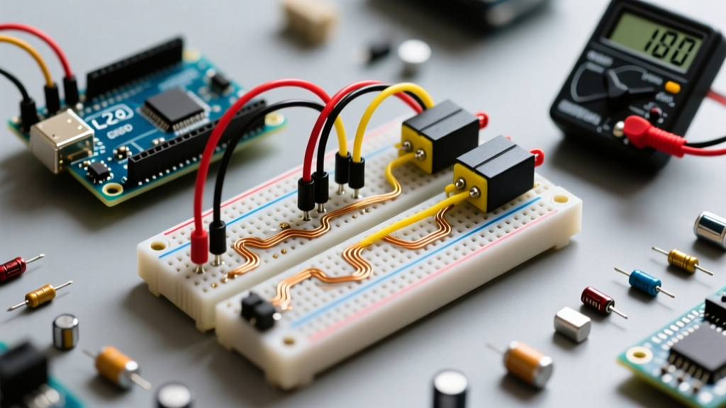
Proper wiring is critical to prevent ground loops and logic errors. Below is the definitive wiring matrix for connecting a single DC motor to Channel A of the L298N module using an Arduino Uno.
| L298N Pin | Arduino Uno Pin | Function / Notes |
|---|---|---|
| ENA | D9 (PWM) | Speed control via PWM. Remove factory jumper cap. |
| IN1 | D8 | Direction control logic A. |
| IN2 | D7 | Direction control logic B. |
| VCC | Battery Positive (+) | Motor power supply (e.g., 7.4V Li-ion 2S pack). |
| GND | Battery Negative (-) & Arduino GND | Critical: Grounds MUST be shared for logic reference. |
| 5V | Arduino 5V (Optional) | Only connect if VCC < 12V and 5V EN jumper is ON. |
Power Supply Selection: Avoiding Brownouts
One of the most common beginner mistakes is attempting to power motors directly from the Arduino's USB 5V line or the onboard 5V regulator. USB ports typically limit current to 500mA, and motors draw high inrush currents that cause voltage sags (brownouts), resetting the microcontroller mid-code.
The Solution: Use a dedicated battery pack for the VCC terminal. A 2S Li-ion battery pack (7.4V nominal, 8.4V fully charged) is the gold standard for beginner robotics. It provides ample current (often 10A+ continuous discharge) and enough voltage to overcome the L298N's 2V drop, delivering a healthy 5.4V to 6.4V to standard 6V TT motors.
The 5V EN Jumper Rule:
- VCC ≤ 12V: Leave the 5V EN jumper ON. The module's onboard 7805 regulator will step down the VCC voltage to 5V to power the L298N logic. You can also wire this 5V pin to your Arduino's 5V pin to power the board itself.
- VCC > 12V: You MUST remove the 5V EN jumper. The 7805 regulator will overheat and fail if the voltage differential is too high. Instead, supply 5V to the logic pin from an external BEC (Battery Eliminator Circuit) or the Arduino's 5V output.
Arduino C++ Control Logic
Controlling the motor requires two steps: setting the direction via digital logic on IN1/IN2, and setting the speed via Pulse Width Modulation (PWM) on ENA. The Arduino analogWrite() Reference details how PWM simulates analog voltage by rapidly switching the pin on and off. A value of 0 is 0% duty cycle (stopped), and 255 is 100% duty cycle (full speed).
// L298N Channel A Pin Definitions
const int ENA = 9;   // Must be a PWM-capable pin (~ symbol on board)
const int IN1 = 8;
const int IN2 = 7;

void setup() {
  pinMode(ENA, OUTPUT);
  pinMode(IN1, OUTPUT);
  pinMode(IN2, OUTPUT);

  // Ensure motor is stopped on boot
  digitalWrite(IN1, LOW);
  digitalWrite(IN2, LOW);
}

void loop() {
  // 1. Move Forward at 75% speed
  digitalWrite(IN1, HIGH);
  digitalWrite(IN2, LOW);
  analogWrite(ENA, 191); // 255 * 0.75 = ~191
  delay(2000);

  // 2. Coast to a stop (Freewheeling)
  digitalWrite(IN1, LOW);
  digitalWrite(IN2, LOW);
  analogWrite(ENA, 0);
  delay(1000);

  // 3. Move Backward at 50% speed
  digitalWrite(IN1, LOW);
  digitalWrite(IN2, HIGH);
  analogWrite(ENA, 127); // 255 * 0.50 = ~127
  delay(2000);

  // 4. Active Braking (Shorts motor terminals internally)
  digitalWrite(IN1, HIGH);
  digitalWrite(IN2, HIGH);
  analogWrite(ENA, 255);
  delay(500);
}
Troubleshooting Common Failure Modes
Even with correct wiring, beginners frequently encounter specific edge cases when using the L298N module:
- Motor Twitches but Won't Turn: This indicates insufficient current. If you are powering the Arduino and motors from a single weak 9V alkaline battery, the voltage sags below the L298N's logic threshold (approx 2.3V) when the motor attempts to draw stall current. Switch to a high-discharge Li-ion or NiMH pack.
- Erratic Arduino Resets: You have a ground loop or missing common ground. The L298N logic circuit needs a shared ground reference with the Arduino. If the battery GND and Arduino GND are not physically connected, the logic signals (IN1/IN2) will float, causing unpredictable behavior and back-EMF spikes that reset the MCU.
- High-Pitched Motor Whine: The default Arduino PWM frequency on pins 9 and 10 is roughly 490Hz, which falls squarely in the human hearing range and causes physical vibration in the motor windings. You can alter the timer prescalers in code to push the PWM frequency to 31kHz (ultrasonic), eliminating the audible whine.
- L298N Chip is Too Hot to Touch: The IC is dissipating massive amounts of power as heat due to the BJT voltage drop. If you are pulling 1.5A continuously with a 2V drop, the chip is burning 3 Watts. Attach a stick-on aluminum heatsink or switch to a MOSFET-based driver.
2026 Perspective: L298N vs. Modern MOSFET Drivers
While the L298N remains the most documented arduino motor driver board on the internet due to its low cost (typically $3 to $5 on Amazon or AliExpress) and ruggedness against accidental shorts, it is fundamentally legacy technology. As of 2026, modern robotics projects heavily favor MOSFET-based H-bridges like the TB6612FNG or the DRV8833.
The Pololu TB6612FNG Dual Motor Driver, for example, costs around $5 to $7 but offers vastly superior efficiency. Because it uses MOSFETs instead of BJTs, its voltage drop is a mere 0.5V at 1A, compared to the L298N's 2V. This means longer battery life, less heat generation, and a physical footprint roughly 20% the size of the bulky L298N module. Furthermore, the TB6612FNG supports PWM frequencies up to 100kHz natively, making it ideal for precision PID control loops in self-balancing robots or CNC plotters.
However, for absolute beginners learning the fundamental concepts of H-bridge logic, direction switching, and PWM duty cycles, the L298N's large screw terminals, visual indicator LEDs, and forgiving physical layout make it an unbeatable educational starting point.