
Why Calibration Dictates Sensor Reliability
Integrating an arduino movement sensor into a robotics, security, or home automation project is only the first step. Out-of-the-box, most motion modules suffer from environmental noise, zero-offset drift, and factory-default thresholds that rarely match real-world conditions. Whether you are tracking a robotic arm's orientation or detecting human presence in a hallway, uncalibrated sensors lead to phantom triggers, missed events, and catastrophic logic failures.
This comprehensive calibration guide bypasses basic wiring tutorials and dives straight into the hardware potentiometers, I2C register maps, and RF shielding tactics required to achieve industrial-grade reliability from consumer-level modules. We will cover the three most dominant movement detection technologies in the maker ecosystem: Passive Infrared (PIR), Inertial Measurement Units (IMU), and Microwave Radar.
Hardware Tuning: The HC-SR501 PIR Sensor
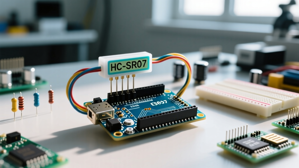
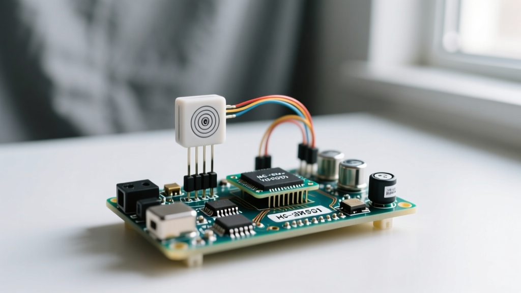
The HC-SR501 relies on a pyroelectric sensor paired with a BISS0001 logic chip to detect changes in infrared radiation. While it features two onboard potentiometers, most users blindly twist them without understanding the underlying RC timing circuits.
Adjusting Sensitivity and Time Delay Potentiometers
The sensitivity potentiometer dictates the comparator threshold voltage. Turning it clockwise increases the detection distance (up to 7 meters) but exponentially increases susceptibility to thermal noise from HVAC vents or direct sunlight. For indoor corridor mapping, set the potentiometer to the 40% mark (roughly 3 turns counter-clockwise from the maximum) to establish a strict 3-meter detection cone.
The time delay potentiometer adjusts the timing capacitor charge rate. At its minimum, the output pin goes low immediately after motion ceases. At its maximum, it holds the HIGH signal for nearly 5 minutes. For security applications, calibrate this to a 4-second delay to prevent the microcontroller from being flooded with interrupt requests during continuous movement.
Overcoming the 'Warm-Up' and False Trigger Failure Modes
Expert Insight: The most common failure mode of the HC-SR501 is phantom triggering caused by MCU switching noise. The module's onboard voltage regulator is notoriously noisy.
To fix this, solder a 100nF ceramic decoupling capacitor directly across the VCC and GND pins on the sensor's PCB. Furthermore, the pyroelectric element requires thermal stabilization. You must implement a mandatory 30-second software lockout in your Arduino setup() routine to allow the BISS0001 chip to calibrate its baseline ambient temperature profile.
Software Offsets: Calibrating the MPU6050 IMU
When your arduino movement sensor needs to track physical orientation, vibration, or acceleration, the MPU6050 6-axis IMU is the standard. However, factory calibration is stored in the ROM, and board-level stress from soldering heat or PCB bending introduces severe zero-offset bias.
Calculating I2C Zero-Offset Drift
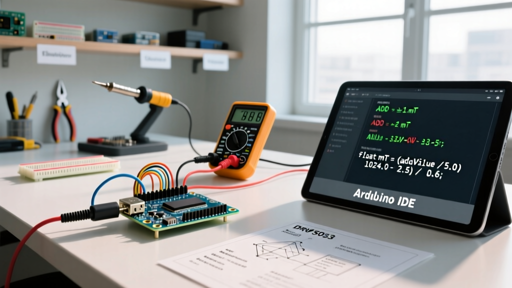
To achieve sub-degree accuracy, you must calculate and write custom offsets to the MPU6050's internal registers. Place the sensor on a machinist-grade bubble level to ensure it is perfectly parallel to the earth's surface. Using the Arduino Wire library, read the raw 16-bit ADC values from the ACCEL_XOUT_H through GYRO_ZOUT_L registers (0x3B to 0x48).
Execute a loop that averages 2,000 consecutive readings while the sensor is perfectly stationary. Divide the accumulated accelerometer X and Y errors by 8, and the Z error by 8 (accounting for the 1G gravity offset). For the gyroscope, divide the accumulated drift by 4. Write these calculated values back to the XG_OFFS_USRH through ZG_OFFS_USRL registers (0x13 to 0x18). This forces the internal Digital Motion Processor (DMP) to subtract your custom baseline before pushing data to the FIFO buffer.
Implementing the Digital Low-Pass Filter (DLPF)
Mechanical vibrations from motors or cooling fans will destroy your IMU data. You must configure the DLPF_CFG register (0x1A). For general human movement tracking, set the DLPF to 0x03, which establishes a 42Hz accelerometer bandwidth and a 40Hz gyroscope bandwidth. This introduces a 4.9ms delay but effectively eliminates high-frequency mechanical noise, yielding incredibly smooth Euler angle calculations.
Microwave Radar: Tuning the RCWL-0516
The RCWL-0516 operates on continuous-wave Doppler radar at roughly 5GHz. Unlike PIR, it detects micro-movements (like breathing) and penetrates drywall. Calibration here is entirely hardware-based, requiring physical component swaps rather than potentiometer twists.
- Sensitivity (R9 Resistor): The default 1MΩ resistor provides a 5-7 meter detection radius. To restrict detection to a single room or a specific doorway, desolder R9 and replace it with a 500kΩ or 300kΩ resistor.
- Repeat Trigger Time (C2 Capacitor): Adding a surface-mount capacitor to the C2 pads extends the time the output remains HIGH after motion stops. A 1µF capacitor yields roughly a 2-second hold time.
- Light Dependent Resistor (LDR) Integration: Soldering an LDR to the designated pads disables the sensor in daylight. Calibrate the LDR threshold by applying a thin coat of clear nail polish over the photoresistor if it is triggering too early during dusk.
Comparative Analysis: Movement Detection Technologies
| Feature | HC-SR501 (PIR) | MPU6050 (IMU) | RCWL-0516 (Radar) |
|---|---|---|---|
| Detection Method | Infrared Heat Delta | Inertial Mass / Capacitance | 5GHz Doppler Shift |
| Calibration Type | Analog Potentiometers | I2C Register Offsets | SMD Component Swaps |
| Wall Penetration | No | N/A (Contact Required) | Yes (Up to 3 drywall layers) |
| Primary Failure Mode | Thermal / RF Noise | Vibration / Gyro Drift | Interference from Wi-Fi Routers |
| Quiescent Current | ~50 µA | ~3.9 mA | ~2.8 mA |
Environmental Interference and Shielding Tactics
Even perfectly calibrated sensors will fail if subjected to unmitigated electromagnetic interference (EMI). When wiring an arduino movement sensor near high-current motor drivers or switching power supplies, the ground plane can experience voltage spikes that mimic sensor signals.
For PIR sensors, wrap the module in copper foil tape (leaving only the Fresnel lens exposed) and connect the tape to a dedicated analog ground. For the MPU6050, ensure your I2C pull-up resistors are tied to a clean, regulated 3.3V rail, not the noisy 5V USB line from the Arduino Uno. Finally, keep microwave radar modules at least 15cm away from 2.4GHz Wi-Fi antennas to prevent harmonic frequency beating, which results in a continuous false-HIGH output state.
Final Verification Testing Protocol
Never deploy a movement sensor to production without executing a 24-hour burn-in test. Log the sensor's output state via serial to an SD card or cloud endpoint. Review the logs for periodic false triggers that correlate with environmental events, such as the building's HVAC system kicking on or direct sunlight crossing the room. True calibration is an iterative loop of hardware adjustment, software filtering, and environmental mapping. By mastering these specific tuning parameters, your movement detection systems will achieve the reliability required for commercial-grade deployments.