
The Multi-Peripheral I2C Bottleneck
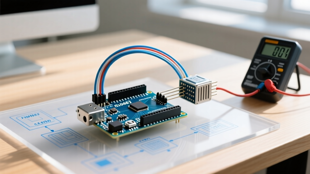
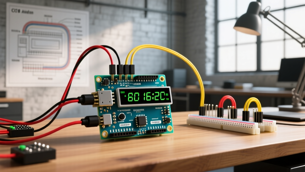
Building a comprehensive environmental or motion-tracking dashboard in 2026 requires moving beyond single-sensor tutorials. When you combine high-speed peripherals like the InvenSense MPU6050 IMU alongside precision environmental sensors like the Bosch BME280, the microcontroller's I2C bus becomes a highly congested highway. In these dense multi-peripheral setups, the Arduino display LCD I2C module remains the undisputed workhorse for localized visual feedback, saving precious digital I/O pins compared to legacy parallel wiring.
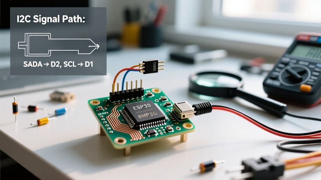
However, simply plugging an LCD into the SDA/SCL lines alongside three other sensors often leads to bus collisions, address conflicts, and silent data corruption. This guide provides an advanced, engineering-focused approach to integrating 16x2 and 20x4 I2C LCDs into complex sensor arrays, addressing power delivery, bus capacitance limits, and non-blocking code architecture.
Anatomy of the I2C LCD Backpack: PCF8574 vs. PCF8574A
Standard HD44780-compatible LCDs do not natively speak I2C. They rely on an I/O expander backpack soldered to the back of the module. Understanding which expander chip is on your specific backpack is the single most critical step in preventing multi-sensor address collisions.
Expert Insight: Never assume your LCD backpack uses the default
0x27address. In multi-sensor arrays, an unrecognized I2C device can stretch the SCL clock line, effectively locking up the entire bus and causing your primary sensors to timeout.
Address Mapping Matrix
According to the Texas Instruments PCF8574 Datasheet, the base address is dictated by the silicon variant and the state of the A0, A1, and A2 jumper pads on the backpack.
| Expander Chip | Base Address Range | Default (Pads Intact) | Common Sensor Conflicts | 2026 Avg. Pricing |
|---|---|---|---|---|
| PCF8574 (NXP/TI) | 0x20 to 0x27 | 0x27 | None (Safe for BME280/MPU6050) | $3.50 (16x2) / $6.00 (20x4) |
| PCF8574A (NXP/TI) | 0x38 to 0x3F | 0x3F | None (Safe for most arrays) | $4.00 (16x2) / $7.50 (20x4) |
Pro-Tip for Dual Displays: If your project requires two independent LCDs (e.g., one for system diagnostics, one for user metrics), intentionally source one PCF8574 board and one PCF8574A board. This guarantees hardware-level address separation without requiring a software I2C multiplexer like the TCA9548A.
Wiring Strategy and Power Delivery Constraints
When wiring an Arduino display LCD I2C module in a multi-sensor array, the primary failure point is rarely the data lines—it is the power rail. A standard 20x4 LCD with an active LED backlight can draw between 60mA and 85mA. Add a relay module, an OLED sensor display, and a cluster of I2C environmental sensors, and your total 5V current draw can easily exceed 250mA.
The Onboard Regulator Thermal Trap
If you are powering an Arduino Uno R3 or Nano via the barrel jack or Vin pin at 9V-12V, the onboard linear regulator (typically an NCP1117) must dissipate the voltage difference as heat. Pushing 250mA through a 7V drop generates nearly 1.75W of thermal load, triggering the regulator's internal thermal shutdown and causing the LCD to flicker or the microcontroller to brownout.
Recommended Power Architecture for 2026 Builds:
- USB-C PD Power: Use modern Arduino boards (like the Uno R4 Minima) that negotiate 5V/3A via USB-C, bypassing the linear regulator entirely.
- External Buck Converter: For legacy 5V boards, use a dedicated LM2596 buck converter module ($1.50) to step down a 12V battery source to 5V, feeding the LCD VCC and sensor VCC rails directly, while tying the grounds together.
- Backlight PWM Control: If you must use the Arduino's 5V pin, remove the jumper on the LCD backpack and wire the backlight LED pin to an Arduino PWM pin. Limit the duty cycle to 40% to drop current draw below 30mA while maintaining readability.
Signal Integrity: Battling Bus Capacitance
The I2C protocol is highly susceptible to parasitic capacitance. The official NXP I2C Specification (UM10204) strictly mandates a maximum bus capacitance of 400pF for standard mode (100kHz) and fast mode (400kHz) operations.
Every jumper wire, sensor breakout board, and the LCD backpack itself adds capacitance. A standard 10cm jumper wire adds roughly 15pF. In a multi-sensor setup with an LCD, a BME280, an SHT31, and an MPU6050, you can easily approach the 300pF threshold, resulting in rounded signal edges and I2C NACK (Not Acknowledged) errors.
Implementing Hardware Pull-Up Resistors
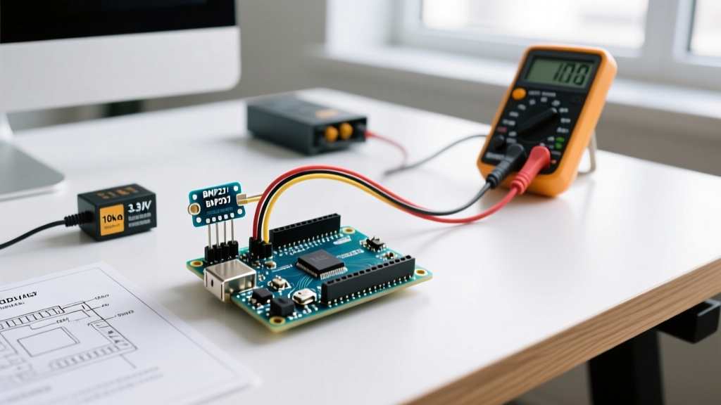
The Arduino's internal pull-up resistors (typically 20kΩ to 50kΩ) are far too weak for a heavily loaded multi-peripheral bus. You must add external pull-up resistors to the SDA and SCL lines.
- Calculate the load: Count the number of I2C devices. Most breakout boards include 4.7kΩ or 10kΩ pull-ups in parallel.
- Target Resistance: For a bus with 3-5 devices and an LCD, aim for an equivalent parallel resistance of 2.2kΩ to 3.3kΩ.
- Physical Placement: Solder a 2.2kΩ resistor between the SDA and 5V lines, and another between SCL and 5V, as physically close to the microcontroller's I2C pins as possible.
Code Architecture: Non-Blocking Display Updates
The most common mistake when integrating an Arduino display LCD I2C with high-speed sensors is using blocking code. The Arduino Wire Library handles I2C transactions synchronously. If you use lcd.print() inside your main loop without timing controls, the microcontroller will spend the majority of its clock cycles updating the display, starving time-critical sensors like the MPU6050 of I2C bus access.
The Millis() State Machine Approach
Human eyes cannot process LCD refresh rates higher than 4Hz (every 250ms). Therefore, the display should only be updated on a strict timer, decoupled from the sensor polling loop.
#include <Wire.h>
#include <LiquidCrystal_I2C.h>

LiquidCrystal_I2C lcd(0x27, 16, 2);
unsigned long lastDisplayUpdate = 0;
const long displayInterval = 250; // Update LCD every 250ms

void setup() {
  Wire.begin();
  Wire.setClock(400000); // Force 400kHz Fast Mode for bus efficiency
  lcd.init();
  lcd.backlight();
}

void loop() {
  // 1. High-speed sensor polling happens here continuously
  readMPU6050Data();
  readBME280Data();

  // 2. Non-blocking LCD update
  unsigned long currentMillis = millis();
  if (currentMillis - lastDisplayUpdate >= displayInterval) {
    lastDisplayUpdate = currentMillis;
    updateLCDDisplay();
  }
}

void updateLCDDisplay() {
  lcd.setCursor(0, 0);
  lcd.print("Temp: ");
  lcd.print(bmeTemp);
  // Clear remainder of line to prevent ghosting
  lcd.print("   ");
}
Notice the Wire.setClock(400000); command. By forcing the bus into Fast Mode, you reduce the time the LCD holds the I2C bus hostage during print operations, freeing up bandwidth for your sensor array.
Troubleshooting Edge Cases in Multi-Peripheral Arrays
When your multi-sensor setup fails silently or outputs garbage data, use this diagnostic matrix to isolate the Arduino display LCD I2C fault.
| Symptom | Root Cause Analysis | Hardware / Software Fix |
|---|---|---|
| LCD lights up, but shows solid white boxes | Contrast potentiometer misconfigured or I2C initialization failed due to bus lockup. | Adjust the blue trimpot on the backpack. If unresolved, add a 100ms delay before lcd.init() to let the bus stabilize. |
| Display works, but BME280 returns NaN | LCD backlight switching causing 5V rail voltage sag, brownouting the 3.3V LDO on the sensor board. | Decouple the LCD backlight power, or add a 100µF electrolytic capacitor across the sensor's VCC/GND pins. |
| Random characters / ghosting on the LCD | I2C bus capacitance exceeding 400pF, corrupting the PCF8574 data latch. | Shorten jumper wires. Add 2.2kΩ external pull-up resistors to SDA/SCL. Reduce I2C clock speed to 100kHz. |
System freezes when lcd.print() is called |
Address collision. The LCD is responding to the same address as another sensor, confusing the Wire library. | Run an I2C Scanner sketch. Cut the A0/A1/A2 pads on the LCD backpack to shift its address away from the conflicting sensor. |
Final Integration Checklist
Before deploying your multi-peripheral setup into an enclosure, verify the following:
- Address Verification: Run Nick Gammon's I2C Scanner to confirm the LCD and all sensors respond to unique addresses.
- Thermal Audit: Run the system for 15 minutes with the LCD backlight at 100%. Touch the Arduino's onboard voltage regulator. If it is too hot to hold, migrate to an external buck converter.
- Cable Management: Keep I2C traces under 30cm (12 inches). If you must route the LCD further away, use a twisted-pair cable for SDA/SCL to reject electromagnetic interference from nearby DC motors or relays.
By respecting the electrical limits of the I2C bus and decoupling your display logic from your sensor polling loops, the Arduino display LCD I2C module transforms from a simple output device into a robust, integrated component of a professional-grade multi-sensor array.