
The Baseline Reality of the HC-SR04 in 2026
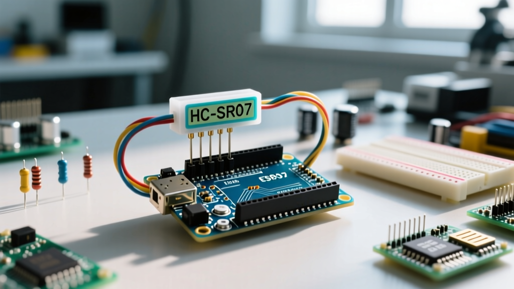
The HC-SR04 remains the most ubiquitous 40kHz ultrasonic transceiver in the DIY and prototyping ecosystem. Walk into any university robotics lab or maker space, and you will find bins of them. However, the out-of-the-box accuracy of these modules is frequently misunderstood. While the datasheet claims a resolution of 3mm and a range of 2cm to 400cm, real-world testing reveals that uncalibrated modules—particularly the $1.20 to $1.80 generic clones that dominate the 2026 market—often exhibit a variance of ±2cm to ±5cm. Genuine or heavily branded variants (like those from Seeed Studio or DFRobot, typically priced around $4.50 to $6.00) offer slightly better internal component tolerances but still suffer from the same fundamental physics limitations.
To transform the HC-SR04 from a crude proximity detector into a precision measurement tool, you must address three critical vectors: environmental acoustics, hardware power integrity, and firmware timing jitter. This guide provides a comprehensive calibration framework for integrating the ultrasonic sensor HC-SR04 with Arduino architectures.
The Physics of 40kHz Acoustic Drift
The most significant source of error in basic HC-SR04 implementations is the assumption of a static speed of sound. Most entry-level Arduino tutorials hardcode the speed of sound to 340 m/s or 343 m/s. However, acoustic velocity in air is highly dependent on temperature and, to a lesser extent, humidity. According to HyperPhysics at Georgia State University, the speed of sound in dry air scales linearly with temperature.
If your Arduino code assumes 343 m/s (the speed of sound at 20°C), but your sensor is operating in a cold warehouse at 5°C, the actual speed of sound is roughly 334 m/s. Over a 100cm distance, this temperature discrepancy introduces a measurement error of nearly 2.7cm. For applications requiring millimeter precision, dynamic temperature compensation is mandatory.
Temperature vs. Speed of Sound vs. Measurement Error
| Ambient Temp (°C) | Actual Speed of Sound (m/s) | Uncalibrated Error at 100cm (Assuming 343 m/s) |
|---|---|---|
| 0°C | 331.3 m/s | +3.51 cm |
| 10°C | 337.4 m/s | +1.70 cm |
| 20°C | 343.2 m/s | -0.05 cm (Baseline) |
| 30°C | 349.0 m/s | -1.72 cm |
| 40°C | 354.7 m/s | -3.38 cm |
Calibration Fix: Integrate a digital temperature sensor like the DS18B20 or an onboard thermistor. Update your distance calculation dynamically using the formula: distance = (pulse_duration * (331.3 + 0.606 * temperature)) / 2. For a deeper dive into acoustic wave propagation, The Physics Classroom provides excellent foundational models on how medium density affects wave velocity.
Hardware-Level Calibration: Power Integrity and Decoupling
A frequently overlooked failure mode in HC-SR04 circuits is voltage sag on the 5V rail. The HC-SR04 does not drive its transmission (TX) transducer directly from the 5V logic supply. Instead, it utilizes an internal voltage multiplier circuit (often a discrete diode-capacitor ladder or a MAX232-equivalent charge pump) to boost the 5V input to approximately 10V–12V. This higher voltage is required to generate a high-pressure 40kHz acoustic burst capable of traveling several meters.
When the module fires the 8-cycle burst, it draws a transient current spike of up to 15mA. If your Arduino's 5V rail has high impedance or is shared with noisy peripherals (like servo motors or relay modules), the voltage will momentarily sag. This sag starves the internal boost converter, resulting in a weak acoustic burst. The echo return is then too faint for the receiver (RX) op-amp to trigger reliably, causing phantom "timeout" or "0cm" readings.
The Decoupling Protocol
- Local Energy Storage: Solder a 10µF to 47µF electrolytic capacitor directly across the VCC and GND pins on the HC-SR04 PCB. This provides the immediate transient current required for the TX burst.
- High-Frequency Filtering: Place a 100nF (0.1µF) ceramic capacitor in parallel with the electrolytic capacitor to filter out high-frequency switching noise from the Arduino's onboard voltage regulator.
- Wiring Gauge: For wire runs exceeding 30cm between the Arduino and the sensor, use 22 AWG stranded wire for power and ground to minimize resistive voltage drop.
Firmware Strategies: Overcoming pulseIn() Limitations
The standard method for reading the HC-SR04 involves the Arduino pulseIn() function. However, as noted in the official Arduino pulseIn() documentation, this function is blocking and relies on software loop counting, which makes it highly susceptible to interrupt jitter. If a background interrupt (like a timer updating a display or reading an encoder) fires while the echo pin is transitioning, pulseIn() can miscalculate the pulse width by several microseconds, translating to millimeters of phantom distance.
Expert Insight: For mission-critical robotics where sensor fusion is required, abandon
pulseIn()entirely. Instead, utilize the ATmega328P's Timer1 Input Capture Unit (ICU). The ICU hardware-latches the exact timer tick the moment the echo pin transitions, completely eliminating software interrupt jitter and providing sub-microsecond timing resolution.
Implementing a Median Filter for Outlier Rejection
Even with perfect timing, acoustic multipath interference (echoes bouncing off adjacent walls or table legs) will occasionally produce massive outliers. A simple moving average will skew your data if an outlier is included. Instead, implement a median filter.
- Trigger the sensor 5 times in rapid succession (with a 10ms delay between reads to allow acoustic dissipation).
- Store the 5 raw microsecond values in an array.
- Sort the array from lowest to highest.
- Return the 3rd value (the median).
This approach completely ignores the occasional 400cm timeout or the 2cm multipath ghost read, stabilizing your output stream dramatically.
Edge Cases and Environmental Failure Modes
Calibration is not just about math and code; it is about understanding the physical limitations of 40kHz acoustics in real-world environments.
The 2cm Blind Spot and Ringing
The HC-SR04 has a physical blind spot of roughly 2cm to 3cm. When the trigger pulse is sent, the TX transducer physically vibrates. It takes a few milliseconds for this mechanical vibration to dampen (a phenomenon known as "ringing"). If an object is closer than 3cm, the echo returns while the RX transducer is still deafened by the mechanical ringing of the TX burst. If your application requires sub-3cm detection, you must switch to a capacitive or infrared Time-of-Flight (ToF) sensor like the VL53L1X.
Specular Reflection and Beam Width
The HC-SR04 emits a conical acoustic beam with an effective angle of approximately 15 degrees. However, sound waves behave like light when hitting smooth, hard surfaces at oblique angles. If the ultrasonic wave strikes a flat wall at a 45-degree angle, the acoustic energy will reflect away from the sensor (specular reflection) rather than bouncing back. The sensor will report a timeout or maximum distance, even though an obstacle is present. To mitigate this in mobile robots, mount sensors at slight downward angles or use multiple overlapping sensors to cover geometric blind spots.
Acoustic Crosstalk in Multi-Sensor Arrays
If you are deploying three or more HC-SR04 sensors on a single chassis, firing them simultaneously will result in catastrophic crosstalk. Sensor A will receive the 40kHz echo generated by Sensor B. You must multiplex the sensors sequentially. Fire Sensor A, wait for the echo (or a maximum timeout of 25ms, which corresponds to the 400cm max range), and then introduce a mandatory 35ms acoustic dead-time before firing Sensor B. This ensures that any residual 40kHz reverberations in the environment have dissipated below the noise floor of the receiver op-amp.
Summary Checklist for Millimeter Precision
- Compensate for temperature dynamically using the 331.3 + 0.606T formula.
- Decouple the VCC rail locally with 10µF and 100nF capacitors.
- Replace blocking
pulseIn()calls with hardware Timer1 Input Capture or, at minimum, a 5-sample median filter. - Enforce a 60ms sequential delay between multiple sensors to prevent acoustic crosstalk.
- Avoid relying on the HC-SR04 for objects closer than 3cm or for detecting soft, sound-absorbing materials like heavy fabrics, which attenuate 40kHz waves severely.
By treating the HC-SR04 not as a simple digital switch, but as a complex analog-acoustic transducer requiring environmental and electrical calibration, you can extract remarkably reliable and precise spatial data for your Arduino projects.