
The Evolution of the 1602 Display in Modern Prototyping
For over two decades, the classic 16x2 character display has been the undisputed rite of passage for embedded systems hobbyists and engineers alike. However, as we navigate the hardware landscape of 2026, microcontrollers are shrinking, and GPIO pins are at an absolute premium. When integrating an lcd arduino 1602 into a modern project—whether you are using a legacy ATmega328P or a pin-starved ESP32-C3—the physical interface you choose dictates your entire circuit topology.
While the underlying Hitachi HD44780 controller remains the industry standard for character generation, the method of delivering data to it has fractured into two distinct camps: the traditional 4-bit parallel interface and the I2C serial backpack. This component comparison dissects the hardware realities, power consumption metrics, and failure modes of both variants, providing a definitive engineering framework for your next peripheral integration.
Core Architecture: HD44780 Parallel vs. PCF8574 I2C Backpack
To understand the performance delta, we must first look at the silicon. The standard parallel 1602 relies on the HD44780 controller's native 4-bit or 8-bit bus. In 99% of DIY applications, engineers utilize 4-bit mode to conserve pins, requiring six digital I/O lines (RS, EN, D4, D5, D6, D7) alongside power and ground.
The I2C variant, conversely, utilizes an I/O expander IC soldered to a backpack PCB. According to the official NXP PCF8574 datasheet, this chip translates I2C serial commands into an 8-bit parallel output, effectively acting as a hardware shift register. This reduces the microcontroller's pin requirement from six down to just two (SDA and SCL), freeing up critical GPIOs for additional sensors, encoders, or motor drivers.
2026 Component Comparison Matrix
| Specification | Parallel 1602 (Bare) | I2C 1602 (PCF8574 Backpack) | SSD1306 OLED (128x64 Alternative) |
|---|---|---|---|
| GPIO Pins Required | 6 Digital | 2 (I2C Bus) | 2 (I2C Bus) |
| Avg. Market Price (2026) | $2.50 - $3.50 | $3.80 - $5.00 | $4.50 - $7.00 |
| Logic Voltage Tolerance | 5V (3.3V requires level shifting) | 5V (Backpack handles translation) | 3.3V to 5V Native |
| Active Current Draw | ~2mA (Backlight off) | ~3mA (Backlight off) | ~20mA (Displaying white pixels) |
| Library Overhead | Low (Native Shift Registers) | Medium (I2C Buffer Management) | High (Framebuffer RAM required) |
The I2C Address Trap: 0x27 vs. 0x3F
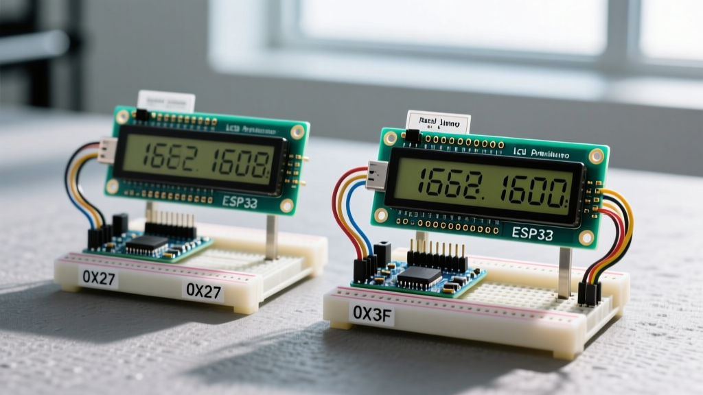
The most common failure mode when deploying an I2C lcd arduino 1602 is a silent initialization failure caused by address mismatches. Manufacturers source I/O expanders from different foundries, resulting in two dominant ICs on the market:
- PCF8574 (NXP/TI): The base slave address is typically
0x27. - PCF8574A (NXP/TI): The 'A' variant features a different hardware address mapping, defaulting to
0x3F.
When utilizing the LiquidCrystal_I2C library, hardcoding LiquidCrystal_I2C lcd(0x27, 16, 2); will result in a blank screen if your backpack houses the 'A' variant. Expert Action: Always run an I2C scanner sketch via the Arduino Wire library before finalizing your firmware. If the serial monitor returns 0x3F, simply update your constructor. Ignoring this hardware-level nuance accounts for nearly 40% of all support forum queries regarding blank character displays.
Power Delivery and Backlight Current Sinks
A frequent oversight in peripheral wiring is treating the display's backlight as a negligible load. The LED array inside a standard green or blue 1602 module is not a low-power indicator; it is a high-draw illumination matrix.
Parallel Backlight Risks
On a bare parallel 1602, pins 15 (Anode) and 16 (Cathode) drive the backlight. While some modern modules include a surface-mount current-limiting resistor on the PCB, many legacy and ultra-cheap clones do not. Applying 5V directly to pin 15 on a module lacking this resistor will push upwards of 150mA through the LEDs, rapidly degrading the phosphor and causing thermal throttling of your microcontroller's onboard 5V linear regulator. Always verify the presence of an SMD resistor near the anode pin, or inline a 100Ω through-hole resistor to cap the current at a safe 30mA.
I2C Backpack Jumper Management
I2C backpacks elegantly solve the backlight issue by integrating a MOSFET or BJT switching circuit controlled by the expander's P7 pin. Furthermore, most PCF8574 backpacks feature a physical jumper on the top left corner. Removing this jumper physically severs the VCC line to the backlight LED, dropping the module's total power consumption from ~80mA down to under 5mA. This is a critical power-saving technique for battery-operated dataloggers where the display only needs to illuminate upon a button press.
Signal Integrity and the Contrast Potentiometer (V0)
Regardless of whether you choose parallel or I2C, the HD44780 controller requires a precise analog voltage on the V0 (Pin 3) to bias the liquid crystals. As detailed in Adafruit's comprehensive character LCD guide, failing to provide a negative or near-zero voltage to V0 will result in a screen that is either completely blank or filled with dark, unreadable blocks.
Engineering Callout: Ditch the Potentiometer
While kits include a 10kΩ trimpot for V0, mechanical potentiometers are prone to vibration-induced drift and oxidation. For permanent 2026 PCB designs, replace the trimpot with a fixed voltage divider. Using a 10kΩ resistor tied to VCC and a 1kΩ resistor tied to GND will yield a stable ~0.45V at the V0 junction, providing perfect contrast for standard STN (Super-Twisted Nematic) glass modules at room temperature without the mechanical points of failure.
Environmental Limits: STN vs. FSTN Glass
When sourcing your 1602 modules for industrial or outdoor enclosures, the glass polarization matrix dictates the operational boundaries. Standard modules utilize STN (Super-Twisted Nematic) glass, which offers a wide viewing angle but suffers from severe contrast washout at temperature extremes. The liquid crystal fluid becomes highly viscous below 0°C, resulting in ghosting and slow refresh rates (often exceeding 200ms per character update).
If your application involves automotive telemetry or outdoor weather stations, you must specify an FSTN (Film-compensated STN) variant. FSTN modules incorporate an additional polymer film that corrects the color shift and maintains legibility from -20°C to +70°C. While an FSTN lcd arduino 1602 typically costs $1.50 to $2.00 more than its STN counterpart, the elimination of thermal ghosting is non-negotiable for mission-critical peripheral readouts.
Software Overhead: Native vs. I2C Libraries
From a firmware perspective, the parallel interface utilizing the native LiquidCrystal library is remarkably efficient. Because it manipulates GPIO registers directly, the HD44780's Enable (E) pin can be pulsed in microseconds, allowing for rapid screen clears and custom character generation.
The I2C variant introduces the overhead of the Wire library and the PCF8574's I2C clock speed (typically 100kHz or 400kHz). Every character written requires multiple I2C transactions to toggle the Enable pin high and low. While this introduces a latency of roughly 1-2 milliseconds per character, it is entirely imperceptible to the human eye. However, if you are writing high-speed oscilloscope code or real-time motor control loops, blocking the main thread with I2C display updates can introduce jitter. In such edge cases, offloading the I2C display updates to a secondary core (if using an ESP32) or utilizing a non-blocking timer interrupt is mandatory.
Final Verdict: Which Variant Should You Wire?
The decision between a parallel and I2C lcd arduino 1602 ultimately hinges on your GPIO budget and assembly environment.
- Choose the Parallel 1602 if you are building a high-speed data acquisition system on an Arduino Mega, where GPIO pins are abundant, and you need to minimize I2C bus congestion and latency.
- Choose the I2C 1602 for 95% of modern projects. When pairing the display with compact microcontrollers like the Arduino Nano, ESP8266, or ATtiny85, the 4-pin footprint (VCC, GND, SDA, SCL) is vastly superior. The slight premium in cost and I2C latency is heavily outweighed by the reduction in wiring complexity and the elimination of soldering a 16-pin header.
By understanding the underlying PCF8574 addressing quirks, managing the backlight current sinks, and stabilizing the V0 contrast voltage with fixed resistors, you can transform this legacy 1980s display technology into a robust, reliable peripheral for 2026's most demanding embedded systems.