
Why Shift from Parallel to I2C for Sensor Projects?
When building environmental monitoring stations or DIY weather hubs, pin economy is critical. A standard parallel HD44780 LCD consumes up to six digital I/O pins (RS, EN, D4, D5, D6, D7). In complex sensor integration projects—where you might simultaneously run a BME280, a PIR motion sensor, and an RTC module—surrendering six pins to a display is inefficient. By utilizing an Arduino LCD with I2C, you reduce the display footprint to just two pins: SDA (Serial Data) and SCL (Serial Clock). This frees up your microcontroller's GPIOs for actual sensor peripherals while sharing the same I2C bus, streamlining your wiring harness and reducing potential points of failure.
Hardware Anatomy: The HD44780 and the I2C Backpack
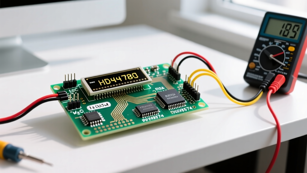
The vast majority of 16x2 and 20x4 character LCDs on the market in 2026 still rely on the Hitachi HD44780 controller. To bridge the gap between the HD44780's parallel interface and the I2C serial bus, manufacturers solder an I/O expander backpack onto the 16-pin header.
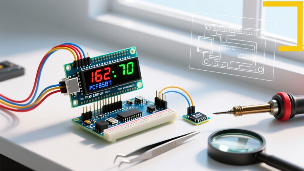
Expert Insight: Not all backpacks are identical. The market is dominated by two NXP I/O expander chips: the PCF8574 and the PCF8574A. While functionally identical, their hardcoded I2C base addresses differ. The PCF8574 typically defaults to
0x27, while the PCF8574A defaults to0x3F. Always verify your specific chip before hardcoding addresses in your firmware.
According to the official NXP PCF8574 datasheet, the chip provides 8 quasi-bidirectional I/O ports. The backpack maps these 8 bits to the LCD's RS, RW, EN, Backlight, and D4-D7 pins, allowing 4-bit mode operation over the I2C protocol.
Component Cost & Sizing Matrix
| Display Type | Resolution | Avg. Cost (2026) | Best Use Case |
|---|---|---|---|
| 16x2 I2C LCD | 16 Cols x 2 Rows | $3.50 - $5.00 | Simple temp/humidity readouts |
| 20x4 I2C LCD | 20 Cols x 4 Rows | $7.00 - $9.50 | Multi-sensor dashboards |
| OLED 128x64 (I2C) | 128x64 Pixels | $6.00 - $8.50 | Graphing sensor trends |
Wiring Matrix: Arduino Uno vs. ESP32
One of the most common failure modes in sensor integration is mismatched logic levels. The HD44780 LCD requires 5V for proper contrast and backlight illumination. However, modern 3.3V microcontrollers like the ESP32 or Arduino Nano 33 IoT require careful handling of the SDA/SCL lines to avoid damaging the SoC.
| LCD Pin | Arduino Uno (5V Logic) | ESP32 (3.3V Logic) | Notes & Warnings |
|---|---|---|---|
| VCC | 5V | 5V (VIN) | Backlight requires 5V; do not use 3.3V. |
| GND | GND | GND | Common ground is mandatory. |
| SDA | A4 | GPIO 21 | Use a bidirectional logic level shifter for ESP32. |
| SCL | A5 | GPIO 22 | Ensure pull-up resistors are on the 3.3V side for ESP32. |
Step-by-Step Sensor Integration Tutorial
For this tutorial, we will integrate a BME280 environmental sensor and display the temperature, humidity, and barometric pressure on a 16x2 Arduino LCD with I2C.
Step 1: Select the Correct Library
Historically, the LiquidCrystal_I2C library by Frank de Brabander was the go-to. However, in 2026, it is highly recommended to use the hd44780 library by Bill Perry, available via the Arduino Library Manager. Unlike older libraries that require manual pin-mapping configurations for clone backpacks, the hd44780 library features an I2Cexp diagnostic class that auto-discovers the I2C address and pin mapping at runtime, eliminating 90% of initialization bugs.
Step 2: Verify I2C Addresses
Before writing your main loop, ensure your devices don't suffer from address collisions. The BME280 typically sits at 0x76 or 0x77. The LCD will be at 0x27 or 0x3F. You can verify this using the standard I2C Scanner sketch. As noted in the Adafruit I2C Address Guide, keeping a master spreadsheet of your project's I2C addresses prevents bus lockups during development.
Step 3: The Integration Code
Below is the optimized C++ code utilizing the hd44780 library and the Adafruit_BME280 library. Notice how the Arduino Wire library handles the underlying I2C bus transactions seamlessly.
#include <Wire.h>
#include <hd44780.h>
#include <hd44780ioClass/hd44780_I2Cexp.h>
#include <Adafruit_BME280.h>

hd44780_I2Cexp lcd; // Auto-detects address and pin mapping
Adafruit_BME280 bme;

const int LCD_COLS = 16;
const int LCD_ROWS = 2;

void setup() {
  Serial.begin(115200);

  // Initialize LCD
  lcd.begin(LCD_COLS, LCD_ROWS);
  lcd.backlight();

  // Initialize BME280 on default I2C pins
  if (!bme.begin(0x76)) {
    lcd.print("BME280 Fail!");
    while (1) delay(10);
  }

  lcd.clear();
}

void loop() {
  float temp = bme.readTemperature();
  float hum = bme.readHumidity();

  lcd.setCursor(0, 0);
  lcd.print("Temp: ");
  lcd.print(temp, 1);
  lcd.print("C");

  lcd.setCursor(0, 1);
  lcd.print("Hum:  ");
  lcd.print(hum, 1);
  lcd.print("%");

  delay(2000); // Sensor read interval
}
Advanced I2C Bus Considerations for Sensor Networks
When your project scales beyond a single LCD and one sensor, you must respect the physical limitations of the I2C bus.
- Bus Capacitance Limit: The I2C specification dictates a maximum bus capacitance of 400pF. Long wires connecting remote sensors or large LCD backplanes add parasitic capacitance. If your bus exceeds 400pF, signal edges degrade, causing corrupted characters on the LCD or dropped sensor packets.
- Pull-Up Resistor Tuning: Most I2C LCD backpacks include 4.7kΩ or 10kΩ pull-up resistors on the SDA/SCL lines. If you add multiple sensor modules (each with their own pull-ups), the parallel resistance drops. If the combined pull-up resistance falls below 2kΩ, the I2C driver may fail to pull the line low. In dense sensor networks, desolder the pull-ups on peripheral modules and rely on a single, strong 2.2kΩ pull-up pair at the master controller.
- Cable Routing: Keep I2C traces under 30cm (12 inches). For remote sensor placement, use twisted-pair cables for SDA/GND and SCL/GND to minimize electromagnetic interference (EMI) from nearby AC wiring or stepper motors.
Troubleshooting Matrix: Fixing Common I2C LCD Failures
Even with auto-discovery libraries, hardware quirks occur. Use this diagnostic matrix to resolve issues rapidly.
| Symptom | Root Cause | Engineering Fix |
|---|---|---|
| Screen is completely black, no backlight. | Insufficient current or 3.3V VCC. | Ensure VCC is connected to a 5V source capable of ≥100mA. |
| Backlight is on, but only top row shows solid white blocks. | Failed initialization / Contrast too high. | Turn the blue trimpot on the backpack counterclockwise until characters appear. |
| Garbage characters or random symbols. | I2C bus noise or missing common ground. | Verify GND is shared. Add 0.1μF decoupling capacitor across LCD VCC/GND. |
| LCD works, but BME280 sensor drops out. | Address collision or bus capacitance. | Check I2C addresses. Reduce wire length or increase pull-up resistor values. |
| Display updates are sluggish or stutter. | Blocking delays in main loop. | Replace delay() with millis() based non-blocking timers. |
Final Thoughts on Peripheral Integration
Mastering the Arduino LCD with I2C is a foundational skill for any embedded systems engineer. By offloading the parallel-to-serial conversion to the PCF8574 backpack, you preserve vital GPIO pins for advanced sensor arrays. Remember to prioritize the hd44780 library for robust auto-discovery, respect the 5V requirements of the LCD backlight, and manage your I2C bus capacitance as your sensor network scales.