
Beyond the Basic Tutorial: Reading the Arduino Hall Sensor Datasheet
Most introductory electronics tutorials treat the Arduino hall sensor as a simple binary switch: bring a magnet close, and the pin goes LOW. While this is true for basic digital sensors like the A3144, it completely ignores the rich, analog data available from linear Hall effect sensors. When your project requires precise magnetic field measurements, position tracking, or current sensing, you must graduate from copy-pasted code and learn to read the manufacturer's datasheet.
In this datasheet explainer, we will deconstruct the Texas Instruments DRV5053, a chopper-stabilized analog Hall effect sensor widely used in precision Arduino projects. By understanding its quiescent voltage, sensitivity drift, and bandwidth limitations, you can write robust C++ code that converts raw ADC readings into accurate milliTesla (mT) measurements.
The Silicon Architecture: What the Datasheet Actually Means
Before wiring the sensor, we need to decode three critical parameters found on page 4 of the DRV5053 datasheet. These specs dictate how the sensor behaves in the real world, far from the idealized conditions of a breadboard.
1. Quiescent Output Voltage ($V_{OUT(Q)}$)
Unlike digital sensors that output 0V or 5V, a linear analog hall sensor outputs a baseline voltage when no magnetic field is present. For the DRV5053OA variant powered at 5V, the datasheet specifies a typical $V_{OUT(Q)}$ of 1.0V.
Expert Insight: Why 1.0V and not 0V? The sensor is designed to measure bipolar magnetic fields (both North and South poles). By biasing the resting output to 1.0V, the sensor can drop toward 0V for a South pole and rise toward 5V for a North pole, eliminating the need for a negative supply rail.
2. Magnetic Sensitivity ($S$)
Sensitivity defines how much the output voltage changes per unit of magnetic flux density. The DRV5053OA boasts a typical sensitivity of 45 mV/mT (millivolts per milliTesla). This means for every 1 mT increase in magnetic field strength, the analog output pin will rise by exactly 0.045V.
3. Chopper Stabilization and Bandwidth
The datasheet highlights an internal 20 kHz chopping frequency. This is a technique used to eliminate the inherent offset voltage drift of the silicon Hall element. However, it introduces a hard bandwidth limit. The internal low-pass filter restricts the sensor's response time to roughly 25 µs, meaning your Arduino cannot accurately sample magnetic fluctuations occurring faster than 20 kHz.
Hardware Integration: Wiring and Decoupling Mandates
A common failure mode in Arduino hall sensor projects is noisy ADC readings. This is rarely the Arduino's fault; it is almost always a violation of the datasheet's decoupling requirements.
The 100nF Bypass Capacitor Rule
The DRV5053 datasheet explicitly mandates a 100 nF ceramic bypass capacitor placed as close to the VCC and GND pins as physically possible. Because the internal chopper circuit switches at 20 kHz, it generates high-frequency noise on the power rail. If you omit this capacitor, that noise couples directly into your analog output, destroying your ADC resolution.
- Dielectric: Use X7R or C0G/NP0 ceramics. Avoid Y5V dielectrics, which suffer from severe capacitance loss under DC bias.
- Placement: On a custom PCB, keep the traces under 2mm. On a breadboard, straddle the capacitor directly across the sensor's power and ground legs.
Wiring to the Arduino Uno / Nano
While the DRV5053 operates from 2.5V to 5.5V, powering it from the Arduino's 5V rail is optimal for maximizing the analog signal-to-noise ratio (SNR) when using the standard 10-bit ADC.
- Pin 1 (VCC): Connect to Arduino 5V.
- Pin 2 (GND): Connect to Arduino GND.
- Pin 3 (OUT): Connect to Arduino A0.
The Math: Converting ADC to MilliTesla (mT)
Translating the Arduino's 0-1023 integer reading into a meaningful physical unit requires precise floating-point math. As of 2026, while 32-bit ARM microcontrollers handle floats natively, 8-bit AVR Arduinos (like the Uno R3 or Nano) still incur a slight performance penalty for float math. However, for magnetic sampling rates under 1 kHz, this overhead is negligible.
Arduino C++ Implementation
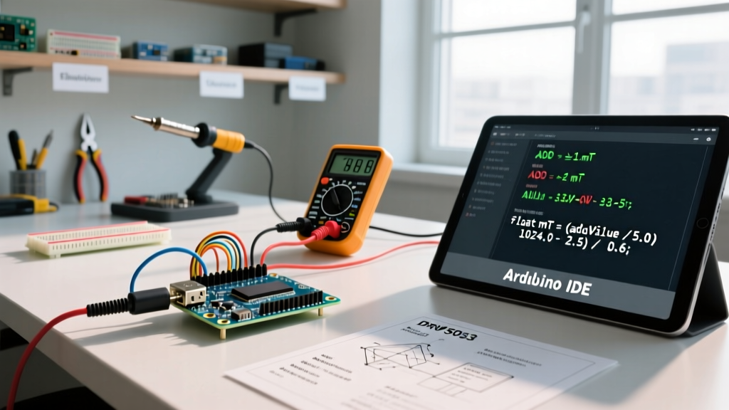
The following code implements the exact transfer function derived from the DRV5053OA datasheet. It accounts for the 5V reference, the 1.0V quiescent baseline, and the 45 mV/mT sensitivity.
// DRV5053OA Analog Hall Sensor Implementation
const int sensorPin = A0;
const float vRef = 5.0;        // Arduino 5V rail (measure with DMM for precision)
const float adcMax = 1023.0;   // 10-bit ADC resolution
const float quiescentV = 1.0;  // V_OUT(Q) at 0 mT
const float sensitivity = 0.045; // 45 mV/mT converted to V/mT

void setup() {
  Serial.begin(115200);
  analogReference(DEFAULT); // Ensure 5V reference is selected
}

void loop() {
  // Read raw ADC and convert to voltage
  int rawAdc = analogRead(sensorPin);
  float voltage = (rawAdc * vRef) / adcMax;

  // Apply datasheet transfer function: B = (Vout - Vq) / Sensitivity
  float magneticField_mT = (voltage - quiescentV) / sensitivity;

  Serial.print('Raw ADC: ');
  Serial.print(rawAdc);
  Serial.print(' | Voltage: ');
  Serial.print(voltage, 3);
  Serial.print('V | Field: ');
  Serial.print(magneticField_mT, 2);
  Serial.println(' mT');

  delay(100); // 10 Hz sampling rate
}
Thermal Drift: The Hidden Datasheet Trap
If you deploy your Arduino hall sensor in an automotive or outdoor environment, you will encounter thermal drift. The datasheet specifies the sensitivity temperature coefficient as -1100 ppm/°C (parts per million per degree Celsius).
Let us calculate the real-world error. If your sensor is calibrated at 25°C and then operates at 65°C (a 40°C increase):
- 40°C × -1100 ppm/°C = -44,000 ppm.
- -44,000 ppm equals a -4.4% shift in sensitivity.
- A true 50 mT field will now read as approximately 47.8 mT.
Actionable Fix: For high-precision 2026 IoT applications, integrate a cheap digital temperature sensor (like the TMP36 or DS18B20) and apply a software compensation multiplier in your Arduino code to correct the Hall sensitivity drift dynamically.
Linear vs. Digital: Sensor Comparison Matrix
Not every project requires an analog output. Below is a technical comparison of popular hall sensors available on the market, contrasting the linear DRV5053 with standard digital and I2C alternatives.
| Sensor Model | Type | Output | Sensitivity / Threshold | Approx. Price (2026) | Best Use Case |
|---|---|---|---|---|---|
| DRV5053OA | Linear Analog | 0.2V - 4.8V | 45 mV/mT | $0.48 | Current sensing, precise proximity |
| SS49E | Linear Analog | 0.4V - 4.5V | 1.4 mV/G (14 mV/mT) | $0.85 | Joystick positioning, legacy designs |
| A3144 | Digital Switch | Open-Drain | Operate: 3.0 mT | $0.15 | RPM counting, limit switches |
| MLX90393 | 3-Axis I2C | Digital (16-bit) | Configurable via I2C | $2.60 | 3D spatial tracking, advanced robotics |
For deeper architectural insights into digital switching thresholds and hysteresis, refer to the Allegro MicroSystems Hall Effect Sensor portfolio, which provides excellent application notes on magnetic hysteresis design.
Summary and Best Practices
Treating an Arduino hall sensor as a simple plug-and-play component is a recipe for noisy data and thermal inaccuracies. By respecting the datasheet's mandates—specifically the quiescent voltage baseline, the strict 100nF X7R decoupling requirement, and the ppm/°C thermal drift coefficients—you can elevate your magnetic sensing projects from hobbyist prototypes to industrial-grade instruments. Always verify your specific sensor suffix (e.g., DRV5053OA vs DRV5053PA), as the sensitivity and quiescent voltages vary wildly between sub-variants.