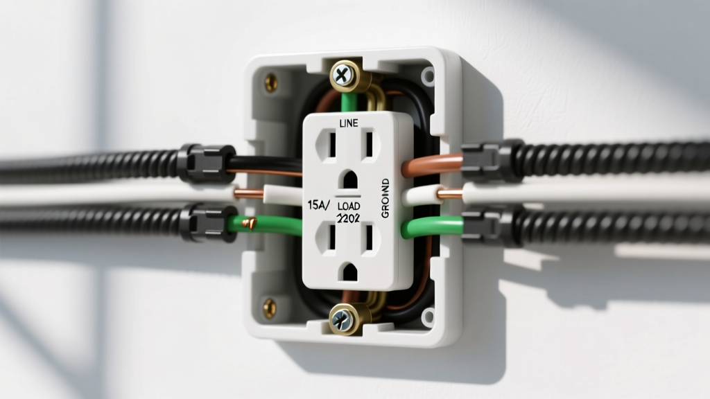

The Anatomy of a Standard Receptacle: Diagram Reference
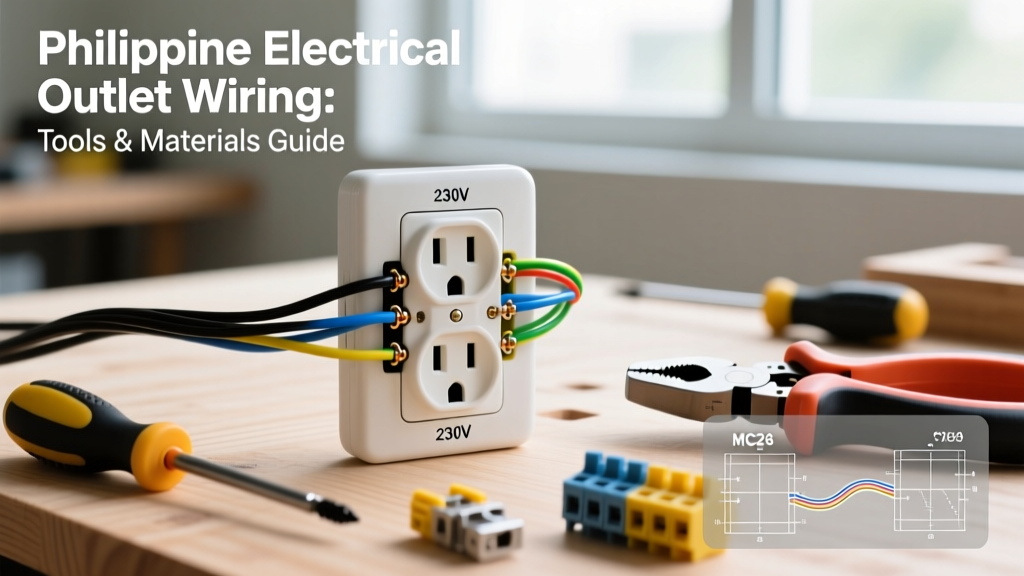
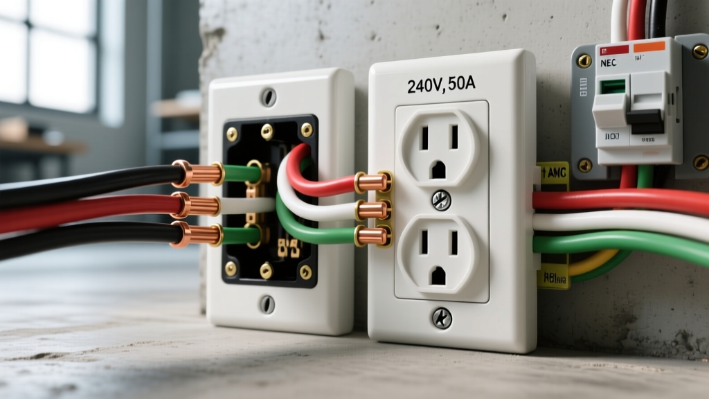
When wiring a new electrical outlet, understanding the physical and electrical anatomy of the receptacle is the first critical step. A standard North American NEMA 5-15R or 5-20R duplex receptacle features three primary terminal types: brass (hot), silver (neutral), and green (ground). As of the 2026 National Electrical Code (NEC) cycle, the requirements for proper termination, torque specifications, and ground-fault protection have become more stringent to mitigate residential fire hazards.
This wiring diagram reference is designed to give DIYers and junior electricians a precise, actionable framework for installing 15-amp and 20-amp receptacles. Whether you are replacing an aging two-prong ungrounded outlet or running a brand-new dedicated circuit for a home workshop, the principles of line and load configuration remain the foundation of safe electrical work.
15-Amp vs. 20-Amp Configuration Matrix
Selecting the correct receptacle and wire gauge is non-negotiable. The National Fire Protection Association (NFPA) outlines these requirements in NEC Article 210. Below is a quick-reference matrix for standard residential branch circuits.
| Specification | 15-Amp Circuit (Standard) | 20-Amp Circuit (Heavy Duty) |
|---|---|---|
| Receptacle NEMA Type | 5-15R (Two parallel slots, one U-ground) | 5-20R (One T-slot, one parallel slot, U-ground) |
| Minimum Wire Gauge | 14 AWG Copper | 12 AWG Copper |
| Breaker Size | 15A Single-Pole | 20A Single-Pole |
| Max Continuous Load | 12 Amps (1,440W at 120V) | 16 Amps (1,920W at 120V) |
| Recommended Model | Leviton Decora 5362 (Residential Grade) | Hubbell HBL5366 (Commercial/Spec Grade) |
Note: You can install 15A receptacles on a 20A circuit (per NEC 210.21(B)(3)), provided there are multiple outlets on the circuit. However, you can never install a 20A receptacle on a 15A circuit.
Preparation: Tooling and Material Specifications
Proper tooling ensures safe, code-compliant terminations. The days of simply tightening a screw until it 'feels right' are over. NEC 2023 and 2026 updates (specifically 110.14(D)) mandate that terminations be tightened to the manufacturer's specified torque.
- Wire Strippers: Klein Tools 11055 (10-20 AWG). Precision stripping prevents nicking the copper conductor, which creates a weak point prone to thermal failure.
- Torque Screwdriver: CDI 401SM Torque Screwdriver set to 14 in-lbs (the standard specification for Leviton and Legrand residential receptacles).
- Voltage Tester: Fluke T+PRO or a reliable non-contact voltage tester (NCVT) like the Klein NCVT-3 to verify the circuit is de-energized.
- Connectors: Ideal Wire-Nut 72B (blue) or Wago 221-413 lever nuts for pigtailing.
- Receptacles: Always opt for 'TR' (Tamper-Resistant) models, which are mandated by the NEC for all 15A and 20A, 125V and 250V non-locking receptacles in dwelling units.
Step-by-Step Wiring Flow: Line and Load Configurations
When wiring a new electrical outlet, you must determine if the outlet is at the end of the run (Line only) or in the middle of a run (Line and Load). Daisy-chaining outlets via the receptacle's own terminal screws is common, but pigtailing is the superior, professional method.
Step 1: De-energize and Verify
Turn off the breaker at the main panel. Test the existing outlet with a plug-in tester or multimeter. Verify 0V between the hot (shorter slot) and neutral (longer slot), and 0V between hot and ground.
Step 2: Strip and Prepare Conductors
Use the built-in wire gauge guide on the back of the receptacle. For 14 AWG wire, strip exactly 5/8 inch of insulation. For 12 AWG, strip 3/4 inch. Exposed copper should not extend past the terminal washer, nor should insulation be tucked under the screw head.
Step 3: Terminate the Ground (Equipment Grounding Conductor)
Loop the bare copper or green wire clockwise around the green grounding screw. The clockwise loop ensures that tightening the screw pulls the loop tighter rather than pushing it out. Torque to 14 in-lbs.
Step 4: Terminate the Neutral (Grounded Conductor)
Connect the white wire to the silver terminal. Pro Tip: If this outlet is part of a Multi-Wire Branch Circuit (MWBC), NEC 300.13(B) strictly prohibits using the receptacle as the continuity path for the neutral. You must use a Wago lever nut or wire nut to pigtail the incoming and outgoing neutrals, then run a single white pigtail to the silver screw.
Step 5: Terminate the Hot (Ungrounded Conductor)
Connect the black wire to the brass terminal. If you are feeding downstream outlets, connect the incoming black (Line) to one brass screw and the outgoing black (Load) to the second brass screw. Torque both to 14 in-lbs.
CRITICAL WARNING: Avoid 'Backstabbing' Never use the push-in spring terminals on the back of standard residential receptacles (often labeled 'INSERT STRIPPED WIRE HERE'). These rely on a small metal spring clip that loses tension over time due to thermal expansion and contraction from electrical loads. This is a leading cause of high-resistance connections and outlet fires. Always use the side-wiring screw terminals or, if available, the screw-clamp backwire plates found on commercial-grade receptacles.
Advanced Diagrams: GFCI and AFCI Integration
Modern electrical codes require advanced protection for specific areas. According to the Consumer Product Safety Commission (CPSC), Ground Fault Circuit Interrupters (GFCIs) have saved thousands of lives by detecting ground-fault currents as low as 4 to 6 milliamps and tripping the circuit in milliseconds.
Wiring a GFCI Receptacle (Line vs. Load)
A GFCI receptacle features two distinct sets of terminals: LINE and LOAD.
- LINE Terminals: These connect to the incoming power from the breaker panel. The black hot wire goes to the brass LINE screw; the white neutral goes to the silver LINE screw.
- LOAD Terminals: These connect to downstream standard outlets, providing them with GFCI protection. If you wire the incoming power to the LOAD terminals by mistake, the GFCI will not reset, and downstream outlets will remain unprotected.
- Grounding: The bare ground wire connects to the green screw. Note that the GFCI does not require an equipment ground to function and protect against shock (though it is required by code to have one for the receptacle itself to be code-compliant in new installations).
AFCI Requirements
Arc Fault Circuit Interrupters (AFCIs) protect against parallel and series arcing, which causes electrical fires. Unlike GFCIs, AFCI protection is typically handled at the breaker panel via an AFCI circuit breaker, rather than at the receptacle itself. Ensure your new outlet circuit is tied to an appropriate Combination Type AFCI breaker if it supplies a bedroom, living room, or hallway, as dictated by NEC Article 210.12.
Troubleshooting Matrix: Failure Modes and Edge Cases
Even with a perfect diagram reference, field conditions can introduce variables. Use this troubleshooting matrix to diagnose issues after wiring a new electrical outlet.
| Symptom / Failure Mode | Probable Cause | Diagnostic & Correction |
|---|---|---|
| GFCI will not reset | Line and Load terminals reversed, or no incoming power. | Use a multimeter to verify 120V at the LINE terminals. Swap wires if they are on LOAD. |
| Outlet sparks when plugging in a load | Loose terminal screw, backstabbed connection, or damaged conductor. | Turn off breaker. Remove outlet, inspect for arcing marks. Re-terminate using side screws and torque to spec. |
| Breaker trips immediately upon energizing | Hot-to-ground short, or neutral-to-ground fault downstream. | Check for pinched wires in the back of the junction box. Ensure bare ground is not touching the brass or silver terminals. |
| Downstream outlets are dead | Broken daisy-chain connection, or GFCI upstream has tripped. | Verify upstream GFCI status. Check LOAD terminals on the upstream device for tight connections. |
Frequently Asked Questions
Can I use 14 AWG wire on a 20-amp breaker?
No. This is a severe fire hazard and a direct violation of NEC 240.4(D). A 20-amp breaker will allow up to 20 amps of current to flow before tripping, but 14 AWG wire is only rated to safely dissipate the heat of 15 amps. The wire insulation will melt and ignite before the breaker trips. Always match 14 AWG to 15A breakers, and 12 AWG to 20A breakers.
Do I need to wrap electrical tape around the receptacle terminals?
While many older electricians wrap the sides of the receptacle with electrical tape to cover the exposed terminal screws, this is not required by the NEC. If you are using a deep junction box and maintaining proper bend radiuses, bare terminals are safe. However, in shallow, crowded metal boxes, a wrap of high-quality 3M Super 33+ vinyl tape can provide an extra layer of protection against accidental shorts to the grounded metal box. For maximum safety and compliance, OSHA guidelines emphasize maintaining clear working space and proper enclosure over reliance on tape.
What is the difference between a 'spec grade' and 'residential grade' outlet?
Residential grade outlets (like the Leviton 5362, costing around $1.50 to $2.50) use lighter internal brass contacts and thinner steel mounting straps. Spec grade or Commercial grade outlets (like the Hubbell HBL5366, costing $4.00 to $7.00) feature thicker internal contact arms that grip plugs much tighter, heavy-duty steel backplates that resist drywall warping, and often include screw-clamp backwiring plates. For high-use areas like kitchens, garages, and workshops, spec grade is highly recommended for longevity.