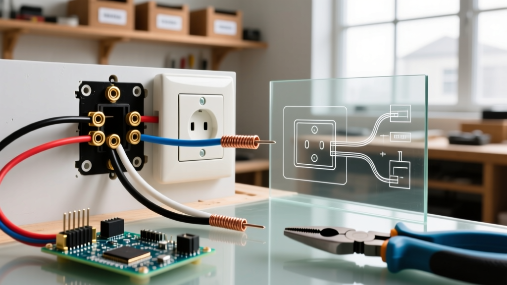

Decoding the '3 Wires' Terminology Trap
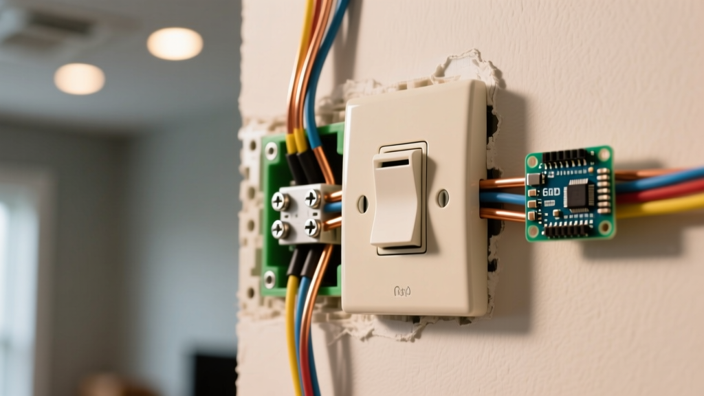
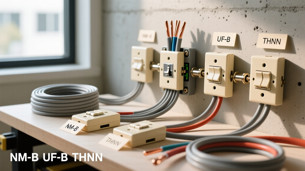
Before picking up a screwdriver, we must clarify a dangerous terminology trap that causes countless DIY electrical fires. When homeowners search for a wiring diagram for light switch and outlet with 3 wires, they are usually referring to the three physical wires found inside a standard 2-conductor NM-B (Romex) cable: Black (Hot), White (Neutral), and Bare Copper (Ground).
However, in professional electrician parlance, a '3-wire cable' actually refers to a 12/3 or 14/3 NM-B cable, which contains four physical wires: Black, Red, White, and Bare Copper. This cable is used for split receptacles, 3-way switch loops, or multi-wire branch circuits (MWBC).
Expert Insight: If your wall box only contains one Black, one White, and one Bare wire, you are working with a 2-conductor cable (14/2 or 12/2). This guide primarily covers this standard 3-physical-wire scenario using a switch/outlet combo device, while also providing the advanced 12/3 split-receptacle diagram for complex setups.
Tools and Materials Required
Skip the cheap, uncalibrated tools. To ensure a safe, NEC-compliant installation that passes inspection, use professional-grade equipment.
| Item | Recommended Model | Approx. Cost (2026) | Purpose |
|---|---|---|---|
| Voltage Tester | Fluke 117 True-RMS Multimeter | $210.00 | Non-contact and precise contact voltage verification |
| Wire Stripper | Klein Tools 11048 (14-10 AWG) | $32.00 | Clean stripping without nicking copper conductors |
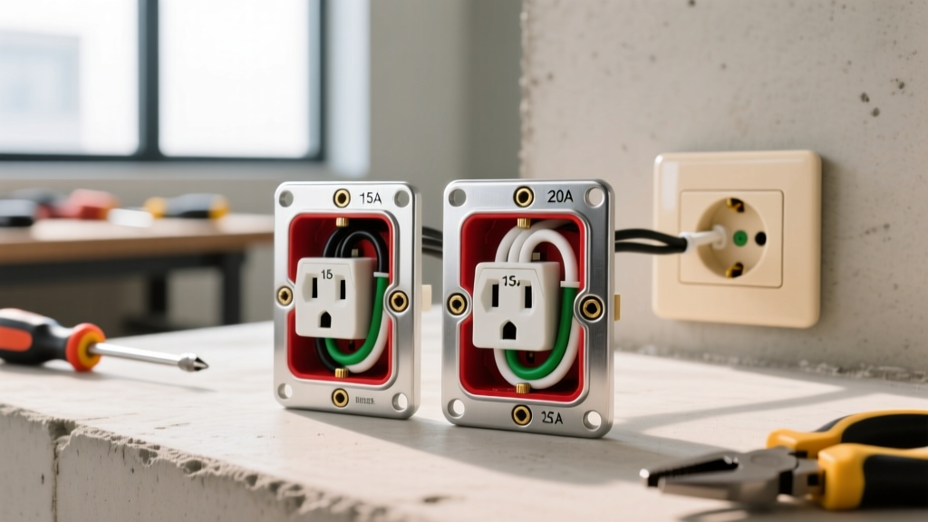
| Combo Device | Leviton 5241-W (15A) or 5245-W (20A) | $14.00 - $18.00 | Single-gang switch and tamper-resistant outlet combo |
| Torque Screwdriver | Klein Tools 69010 | $145.00 | NEC 110.14(D) compliant terminal tightening |
| Wire Connectors | Ideal 33 Orange (14-10 AWG) | $8.00 / box | Secure pigtailing for ground and neutral wires |
Pre-Installation Safety & NEC Compliance
According to the National Electrical Code (NFPA 70), any new or replaced receptacle in kitchens, bathrooms, garages, and outdoor locations must be GFCI protected (NEC 210.8), and most living space circuits require AFCI protection (NEC 210.12). If your combo device is in a bathroom, you must use a GFCI combo switch/receptacle (like the Leviton 7299-W), not a standard combo device.
Furthermore, the Electrical Safety Foundation International (ESFI) stresses that verifying the absence of voltage is the single most critical step before touching a conductor. Never rely solely on a wall switch being in the 'off' position to assume a circuit is dead.
Step-by-Step Installation: Standard 3-Wire Setup (14/2 or 12/2 NM-B)
This scenario assumes you are installing a single-gang switch/outlet combo device where the switch controls a nearby light fixture, and the outlet remains constantly hot. The wall box receives power from the panel via one 14/2 or 12/2 cable (3 physical wires), and sends power to the light via another 14/2 or 12/2 cable.
Step 1: Isolate and Verify Power
- Turn off the corresponding 15A or 20A breaker at the main service panel.
- Use your Fluke 117 multimeter to test between the Black and White wires, then Black and Ground. The reading must be exactly 0.0V.
- Test your multimeter on a known live circuit to confirm the tool is functioning correctly.
Step 2: Prepare the Conductors
Using the Klein Tools 11048, strip exactly 3/4 inch of insulation from the Black and White wires. Stripping too little leaves exposed copper outside 2026 NEC strictly prohibits. If the wire is damaged or kinked, snip it back and re-strip.
Step 3: Bond the Grounding System First
Always wire the ground first. If you are using metal boxes, the bare copper must also pigtail to the box's green grounding screw. Twist the bare wires from both the line and load cables together with a bare copper pigtail, secure with an Ideal 33 wire nut, and attach the pigtail to the Green grounding screw on the combo device.
Step 4: Connect the Neutral (White) Wires
Connect all White neutral wires together using a wire nut. Add a White pigtail and connect it to the Silver terminal screw on the outlet side of the combo device. Note: The switch side of a standard combo device does not use a neutral wire unless it is a smart switch requiring a neutral return.
Step 5: Wire the Hot (Black) Conductors and the Break-Off Fin
This is where most DIYers fail. Look at the brass (hot) side of the Leviton combo device. You will see a small metal connecting fin between the top and bottom brass screws.
- If the outlet must be ALWAYS HOT and the switch controls a separate light: Leave the brass fin intact. Connect the incoming Line Hot (Black) to the bottom brass screw. Connect the Load Hot (Black going to the light) to the top brass screw (or the designated switch lead wire, depending on the specific model's internal routing).
- If the switch controls the outlet (switched receptacle): Use needle-nose pliers to snap the brass fin off. Connect the Line Hot to the bottom brass screw (outlet side) and the Switched Hot to the top brass screw (switch side).
Step 6: Torque and Secure
NEC 110.14(D) requires terminations to be tightened to the manufacturer's specified torque. While often ignored in older homes, modern inspections require it. Leviton specifies 14 in-lbs for their 15A/20A terminal screws. Use a calibrated torque screwdriver to secure the connections, then carefully fold the wires into the back of the gang box, ensuring no bare ground wires touch the brass or silver terminal screws.
Advanced Scenario: The 12/3 NM-B Split Receptacle
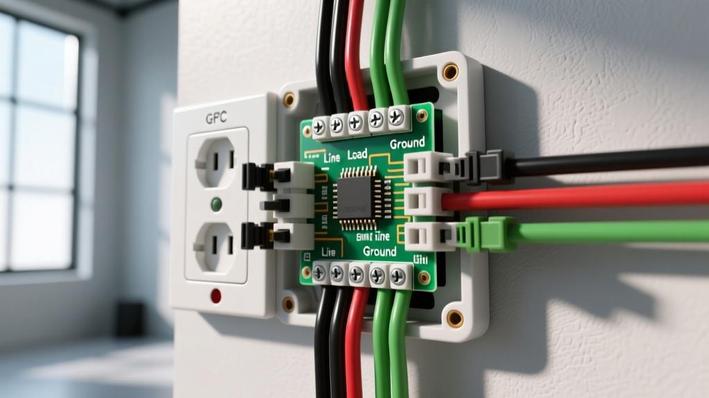
If your search intent was actually for a true '3-wire cable' (12/3 NM-B containing Black, Red, White, and Ground), you are likely wiring a split receptacle. This is common in kitchens and living rooms where the top outlet is always hot, but the bottom outlet is controlled by a wall switch.
As noted by the U.S. Consumer Product Safety Commission (CPSC), multi-wire branch circuits (MWBCs) carry unique shock hazards if the breaker is not properly handled.
- The Breaker Rule: A 12/3 MWBC must be connected to a double-pole 20A breaker, or two single-pole breakers with a handle tie. This ensures both the Black and Red hot legs are disconnected simultaneously during maintenance.
- Break the Fin: You must snap the brass fin on the hot side of the receptacle.
- Terminate Hots: Connect the Black wire to the top brass screw (always hot) and the Red wire to the bottom brass screw (switched hot).
- Neutral: The single White wire connects to the silver screw. It carries the unbalanced return current of both the Black and Red legs.
Troubleshooting Common Failure Modes
Even with a perfect wiring diagram, physical installation errors occur. Here is how to diagnose them:
- Symptom: The outlet works, but the switch does not turn on the light.
Fix: You likely connected the Load Hot (going to the light) to the neutral (silver) side, or the brass fin was left intact when it should have been broken for a switched loop. - Symptom: The breaker trips immediately upon resetting.
Fix: You have a dead short. Check if a bare ground wire is touching a brass terminal, or if the Black and White wires are reversed at the device or upstream. - Symptom: The GFCI combo device will not reset.
Fix: GFCI combo devices require a Line and Load connection. Ensure the incoming power is on the 'LINE' terminals and the downstream load is on the 'LOAD' terminals. Reversing these prevents the internal self-test from passing.
Frequently Asked Questions
Can I use 14 AWG wire on a 20-Amp breaker?
No. NEC 240.4(D) strictly limits 14 AWG copper to a maximum 15-Amp breaker. If your circuit is protected by a 20-Amp breaker, you must use 12 AWG wire and a 20-Amp rated combo device (which features a T-shaped neutral slot to accept 20-Amp plugs).
Do I need to wrap electrical tape around the terminal screws?
While many older electricians wrap friction tape around the sides of receptacles to cover exposed terminal screws, modern best practice dictates using deep-gang boxes or properly sized device boxes that allow the device to sit flush without exposed terminals. If the box is shallow and terminals are within 1/4 inch of the metal box edge, apply high-quality vinyl electrical tape (like 3M Super 33+) to prevent short circuits.