
The Great Debate: Electrical Outlet vs Receptacle Defined
If you have ever browsed the aisles of an electrical supply house or debated wiring codes on a forum, you have likely encountered the electrical outlet vs receptacle terminology clash. While homeowners and even some apprentice electricians use these terms interchangeably, the National Electrical Code (NEC) draws a rigid, legally binding distinction between the two. Understanding this difference is not just semantic pedantry; it fundamentally dictates how you approach circuit design, load calculations, and physical installation.
NEC Article 100 Definitions:
Outlet: A point on the wiring system at which current is taken to supply utilization equipment.
Receptacle: A contact device installed at the outlet for the connection of an attachment plug.
To put it simply: A hardwired ceiling light fixture is an outlet, but it is not a receptacle. A duplex wall plug is a receptacle installed at an outlet (the wall box). When we discuss 'installing an outlet' in DIY circles, we are technically installing a receptacle device into an outlet box. For the 2026 NEC cycle, understanding these definitions is critical when applying rules like AFCI protection (which applies to the entire outlet branch circuit) versus TR (Tamper-Resistant) requirements (which apply specifically to the receptacle device).
Comparison Matrix: Outlet vs. Receptacle
| Characteristic | Electrical Outlet | Receptacle |
|---|---|---|
| Core Function | Termination point for power delivery | Interface for removable plug connections |
| Physical Examples | Light fixture, hardwired HVAC, wall box | Duplex 15A/20A wall plug, L6-20R twist-lock |
| NEC Code Focus | Box fill, circuit routing, AFCI/GFCI zones | TR compliance, spacing, torque, grounding |
| Typical Cost (2026) | $2.00 - $15.00 (for the outlet box) | $3.50 (standard TR) to $45.00 (GFCI/AFCI) |
Pre-Installation: Code Requirements & Tool Selection
Before we physically wire a receptacle into an outlet box, you must ensure compliance with current safety standards. The Electrical Safety Foundation International (ESFI) heavily advocates for Tamper-Resistant (TR) receptacles in all residential dwellings, a mandate strictly enforced in the NEC to prevent pediatric shock incidents. Furthermore, modern code requires precise torque on terminal screws to prevent thermal expansion failures.
Required Tools & Materials
- Device: Leviton T5320-W (15A, 125V, Tamper-Resistant Duplex Receptacle) - Approx. $3.50.
- Voltage Tester: Fluke T6-600 Electrical Tester (for non-contact and contact verification).
- Wire Strippers: Klein Tools 11055 (calibrated for 14 AWG and 12 AWG solid copper).
- Torque Screwdriver: Klein Tools 32500 or Wiha 28503, calibrated to 14 in-lbs (inch-pounds).
- Outlet Box: Carlon B114R (14 cubic inch, non-metallic, new work) or equivalent remodel box.
Step-by-Step: Installing a 15A TR Receptacle at a Wall Outlet
Follow this precise procedure to install a standard 15A receptacle. This guide assumes you are working with a standard 120V, 60Hz branch circuit utilizing 14 AWG or 12 AWG copper wire.
Step 1: Power Verification & Box Prep
- Kill the Circuit: Turn off the corresponding breaker at the main panel. Apply a lockout/tagout (LOTO) device if you share the home with others.
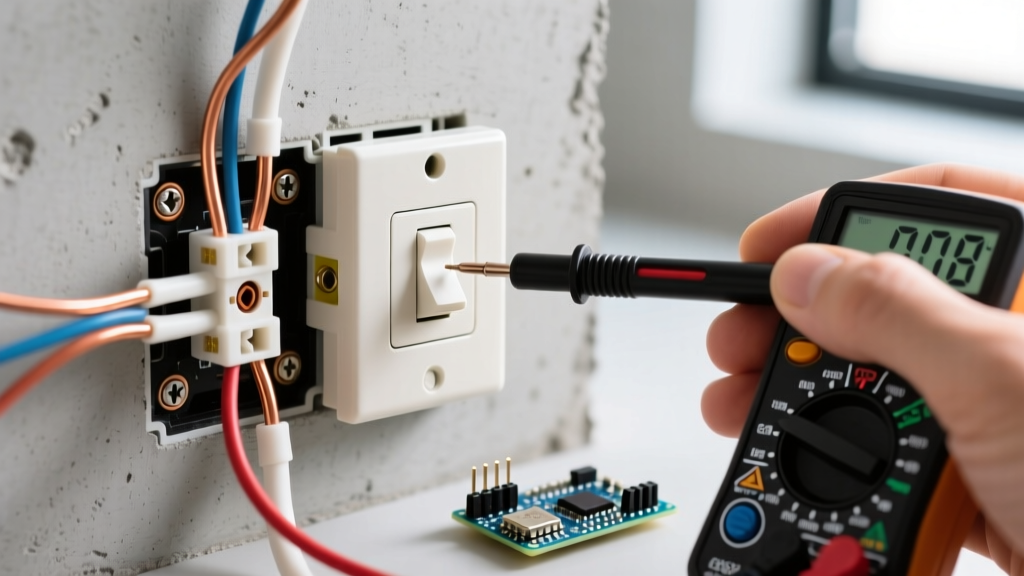
- Test for Dead: Insert the Fluke T6-600 probes into the existing receptacle slots. Verify 0.0V on both Line-to-Neutral and Line-to-Ground.
- Prepare the Outlet Box: Ensure the outlet box is free of drywall mud, debris, and protruding nails. If using a non-metallic box, verify the internal cable clamps are secure and that you have at least 1/4 inch of cable sheath entering the box to satisfy NEC 300.14 (minimum 3 inches of free conductor length beyond the box).
Step 2: Wire Stripping & Preparation
Improper wire stripping is the leading cause of arc faults and short circuits. Using your Klein 11055 strippers, strip exactly 3/4 inch of insulation from the black (hot), white (neutral), and bare (ground) wires.
Expert Tip: Do not nick the copper conductor. A nicked 12 AWG wire creates a structural weak point that can snap when folded into the outlet box, leading to an open-circuit failure behind the wall.
Step 3: Termination Strategy (Side-Wire vs. Back-Wire)
When wiring the receptacle, you will notice three potential connection methods on the Leviton T5320-W:
- Push-In (Backstab): Avoid at all costs. These rely on a tiny internal brass spring shim that bites into the wire. Under heavy continuous loads (like space heaters), the shim loses tension, causing high-resistance arcing and melted yokes.
- Side-Wire (Screw Terminal): Wrap the wire clockwise around the terminal screw. Tighten using your torque screwdriver.
- Back-Wire (Clamp Plate): Insert the straight stripped wire into the rear hole, and tighten the screw which pulls a brass pressure plate against the wire. This is the preferred method for DIYers and pros alike, as it requires no looping and provides maximum surface contact.
Step 4: Torque-Tightening to NEC Standards
According to the National Fire Protection Association (NFPA) and NEC Article 110.14(D), listed torque specifications must be followed. Most standard 15A/20A receptacles require 14 in-lbs of torque. Set your torque screwdriver to the manufacturer's spec (printed on the back of the Leviton device). Tighten until the driver clicks. This prevents the 'cold flow' of copper, ensuring the connection does not loosen over years of thermal cycling.
Step 5: Yoke Alignment & Grounding
- Connect the bare copper ground wire to the green grounding screw on the receptacle yoke.
- Neatly fold the wires into the outlet box using a 'Z-fold' or 'U-fold' method, pushing the ground wires to the very back, followed by the neutrals, and finally the hots.
- Seat the receptacle yoke against the drywall. Use the elongated mounting holes to plumb the device before driving the 6-32 machine screws into the box ears.
- Attach a polycarbonate or nylon unbreakable cover plate (e.g., Leviton 80401-W), tightening the center screw just enough to seat the plate without cracking it.
Common Edge Cases & Troubleshooting
Multi-Wire Branch Circuits (MWBC)
If your outlet box contains two hot wires (one black, one red) sharing a single white neutral, you have an MWBC. Warning: You must break the hot-side brass tab on the receptacle yoke using needle-nose pliers before installation. Failing to break this tab will create a dead short across the two opposing 120V legs, resulting in an immediate 240V explosion when the breaker is energized.
Reverse Polarity & Open Grounds
After restoring power, test the receptacle with a 3-light GFCI tester (like the Gardner Bender GFI-3501).
- Two Amber Lights: Correct wiring.
- One Amber, One Red: Reverse polarity. The hot and neutral are swapped at the receptacle or upstream.
- One Amber Light Only: Open ground. The equipment grounding conductor is disconnected.
Frequently Asked Questions
Can I install a 20A receptacle on a 15A circuit?
No. NEC Table 210.21(B)(3) strictly prohibits installing a 20A receptacle (which features a T-slot neutral) on a 15A breaker circuit. However, you are permitted to install standard 15A receptacles on a 20A circuit, provided there is more than one receptacle outlet on that circuit.
Do I need a GFCI receptacle in every room?
GFCI protection is required at specific outlets, not every room. As of the latest NEC updates, GFCI protection is mandated for receptacles in kitchens, bathrooms, garages, outdoors, crawl spaces, unfinished basements, laundry areas, and within 6 feet of sinks. You can achieve this by installing a GFCI receptacle at the first outlet in the series and wiring downstream receptacles to its 'LOAD' terminals.