
The Critical Importance of Proper Plug Termination
When it comes to residential and commercial electrical systems, the integrity of a connection is only as strong as its weakest termination point. Wiring an electrical plug—specifically the standard North American NEMA 5-15P 15-amp, 125-volt attachment plug—might seem like a rudimentary task, but improper execution is a leading cause of high-resistance connections, arc faults, and subsequent electrical fires. According to the National Fire Protection Association (NFPA), loose or improperly torqued electrical connections generate excessive heat due to increased resistance, which can ignite surrounding combustible materials.
This comprehensive, step-by-step guide moves beyond basic DIY advice. We will cover the precise measurements, torque specifications, and failure-mode prevention techniques required to wire a replacement plug like a seasoned electrician, ensuring compliance with modern safety standards and the OSHA wiring methods guidelines for strain relief and termination.
Required Tools and Materials
Do not rely on dull utility knives or standard screwdrivers for this task. Precision tools prevent conductor damage and ensure lasting connections.
- Replacement Plug: Leviton 5266-C (15A, 125V, NEMA 5-15P) or Hubbell 5266C. These industrial-grade plugs feature robust cord grips and deep terminal wells.
- Wire Strippers: Klein Tools 11055 (10-18 AWG) or Knipex Automatic Wire Strippers. These prevent nicking the copper conductor.
- Torque Screwdriver: Wera 05073575001 or a standard dial torque driver capable of measuring 10 to 20 inch-pounds (in-lbs).
- Tester: Gardner Bender GRT-501 Receptacle and GFCI Tester to verify polarity post-installation.
Anatomy of a NEMA 5-15P Plug: Terminal Mapping
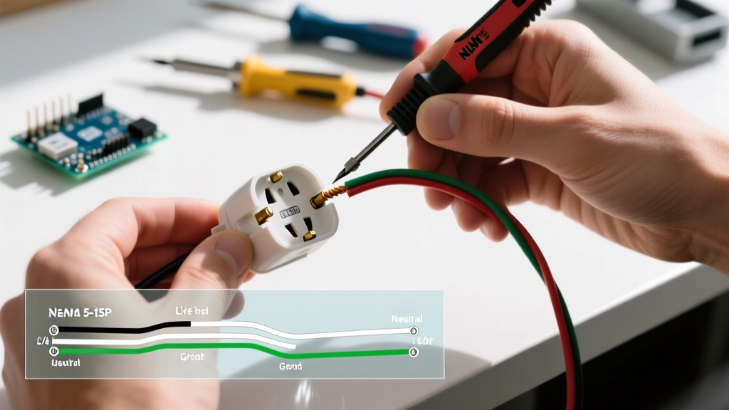
Before stripping any wire, you must understand the internal architecture of the plug. Reversing polarity or misidentifying the ground path compromises the safety of the entire appliance circuit.
| Wire Insulation Color | Terminal Screw Color | Plug Blade | Function | Target Torque |
|---|---|---|---|---|
| Black (or Red/Blue) | Brass (Gold) | Shorter, Narrow Flat Blade | Ungrounded (Hot) Conductor | 12 - 14 in-lbs |
| White (or Gray) | Silver (Nickel) | Longer, Wide Flat Blade | Grounded (Neutral) Conductor | 12 - 14 in-lbs |
| Green (or Bare Copper) | Green | Round U-Shaped Pin | Equipment Grounding Conductor | 12 - 14 in-lbs |
Step-by-Step Installation Procedure
Step 1: Outer Jacket Stripping (The 1.5-Inch Rule)
The most common mistake novices make is stripping too much or too little of the cable's outer PVC jacket. The Measurement: Score and remove exactly 1.5 inches of the outer jacket. The Why: If you strip less than 1.5 inches, the internal cord grip will clamp down on the individual colored conductors rather than the thick outer jacket, leading to insulation crush and short circuits. If you strip more than 2 inches, you leave bare conductors exposed inside the plug housing, creating an arc-flash hazard.
Step 2: Conductor Preparation and Stripping
Separate the three internal conductors and strip exactly 0.5 inches (1/2 inch) of insulation from the tip of each wire. Use the precise gauge hole on your wire strippers (typically 14 AWG for standard 15A lamp cords, or 12 AWG for heavier appliance cords). Critical Inspection: Hold the stripped wire up to the light. If you see any deep nicks or scratches in the copper, cut it off and re-strip. A nicked conductor creates a localized hot spot under load due to reduced cross-sectional area.
Step 3: Forming the 'Shepherd's Hook'
Using needle-nose pliers, bend the exposed copper into a tight, uniform 'U' shape, commonly called a shepherd's hook. The Golden Rule of Direction: The hook MUST curve clockwise. When you wrap the wire around the terminal screw and tighten it (which also turns clockwise), the screw head will pull the wire loop tighter around the shaft. If you loop it counter-clockwise, the rotation of the screw will push the wire out from under the head, resulting in a loose connection and eventual thermal failure.
Step 4: Termination and Precision Torquing
Slide the shepherd's hook under the terminal screw head and the attached square washer. Ensure no stray copper 'whiskers' are protruding from the sides of the terminal well. Using your torque screwdriver, tighten each screw to 14 inch-pounds.
Safety Warning: Do not overtighten. The terminal screws on standard 15A plugs are made of soft brass. Exceeding 16 in-lbs risks stripping the threads or shearing the screw head off entirely. Conversely, under-torquing (below 10 in-lbs) allows the copper to 'cold flow' away from the screw head over time, increasing resistance.
Step 5: Securing the Cord Grip (Strain Relief)
Before closing the housing, route the cable through the plug's internal cord grip clamp. The clamp must bite down firmly on the outer PVC jacket, not the individual colored wires. Tug firmly on the cable; it should not slide into or out of the plug housing. As noted by the U.S. Department of Energy's electrical safety guidelines, proper strain relief is mandatory to prevent mechanical stress from transferring directly to the delicate terminal screws during everyday use.
Step 6: Assembly and Polarity Verification
Snap or screw the plug housing halves together. Ensure no wires are pinched between the plastic seams. Plug the newly wired cord into a live receptacle and insert your Gardner Bender GRT-501 tester into the female end of the cord. The tester should indicate 'Correct' (typically two amber lights illuminated). If it reads 'Hot/Neutral Reverse,' unplug immediately, open the plug, and swap the black and white wires on their respective brass and silver terminals.
Troubleshooting Common Failure Modes
Even with careful execution, issues can arise. Use this diagnostic matrix to identify and correct hidden flaws before energizing the circuit.
| Observed Symptom | Root Cause | Corrective Action |
|---|---|---|
| Tester reads 'Open Ground' | Green wire not making contact with the green terminal, or bare wire is too short. | Re-strip the ground wire to exactly 0.5 inches and ensure the U-hook is fully seated under the screw head. |
| Plug feels warm after 10 mins of use | Under-torqued terminal screws or nicked conductors reducing current capacity. | Disassemble, inspect copper for nicks, replace wire if damaged, and re-torque to 14 in-lbs. |
| Intermittent power loss when cable is moved | Cord grip clamping on inner conductors instead of the outer jacket. | Loosen the cord grip, push the cable further in until the jacket is under the clamp, and retighten. |
| Visible scorch marks inside plug housing | Copper 'whiskers' bridging the gap between the hot (brass) and neutral (silver) terminals. | Trim stray strands flush with the insulation before forming the shepherd's hook. |
Final Thoughts on Longevity and Safety
Wiring an electrical plug is a foundational skill that bridges the gap between a safe electrical system and a hazardous one. By adhering to exact stripping measurements, utilizing the clockwise shepherd's hook technique, and applying precise torque to the terminal screws, you ensure a low-resistance, mechanically sound connection that will withstand years of physical and thermal stress. Always prioritize industrial-grade components like the Leviton 5266-C over cheap, unbranded alternatives found in discount bins, as the internal brass thickness and plastic housing quality directly dictate the lifespan of your termination.