
Why Disconnect an Outlet for Diagnostics?
In residential and commercial wiring, standard 15A and 20A receptacles are rarely isolated endpoints. They are typically daisy-chained in series, acting as junction points for downstream devices. When a circuit breaker trips repeatedly, a GFCI refuses to reset, or a downstream outlet reads 'dead,' the root cause is often hidden behind the faceplate of an upstream receptacle. Knowing how to disconnect an electrical outlet properly is a foundational troubleshooting skill that allows you to isolate faults, eliminate variables, and pinpoint wiring failures without blindly replacing components.
Safety Directive: According to the Occupational Safety and Health Administration (OSHA), de-energizing live parts and verifying the absence of voltage is mandatory before any physical contact with termination points. Never rely solely on a non-contact voltage tester for final verification.
Phase 1: Pre-Disconnect Diagnostic Toolkit
Before removing a single screw, assemble the correct diagnostic tools. Using substandard testers is the leading cause of misdiagnosis and electrical shock in 2026.
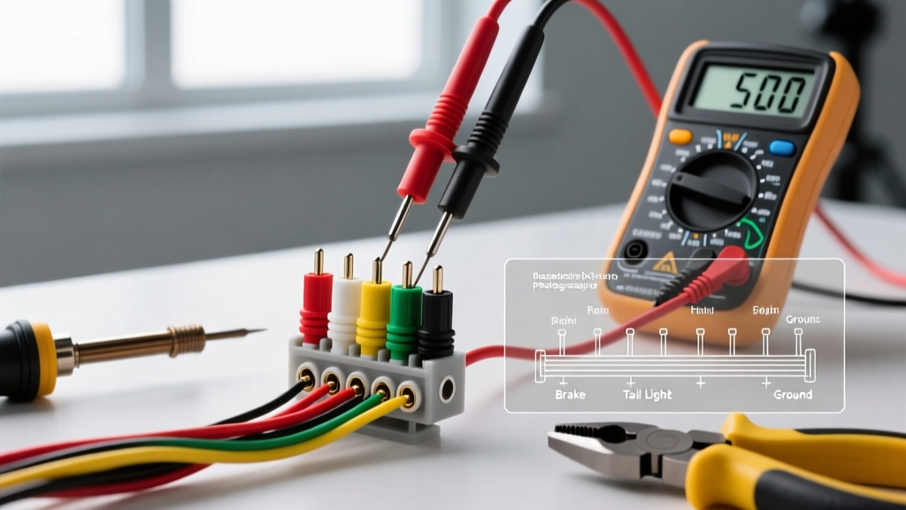
- True RMS Multimeter: The Fluke 117 (~$200) is the industry standard for accurately reading phantom voltages and verifying true zero-potential.
- Non-Contact Voltage Tester (NCVT): Klein Tools NCVT-3 (~$35) for initial field mapping and dual-range detection (12-1000V).
- Insulated Wire Nuts / Lever Connectors: Wago 221-412 lever nuts (~$1.20 each) are vastly superior to standard twist-on caps for temporary troubleshooting isolation, allowing rapid connect/disconnect without stripping copper.
- Torque Screwdriver: Milwaukee 48-22-2910 VDE (~$85) to ensure code-compliant reconnection later.
Phase 2: Step-by-Step Safe Disconnection
Follow this exact sequence to isolate the receptacle from the branch circuit. This method prevents arc faults and protects downstream electronics.
- Kill the Branch Circuit: Identify the correct breaker in the panel. If the outlet is dead and the breaker hasn't tripped, you may need a circuit tracer (like the Klein RT210) to find the source.
- Initial NCVT Sweep: Scan the faceplate and the gap between the yoke and the drywall to confirm the primary field is de-energized.
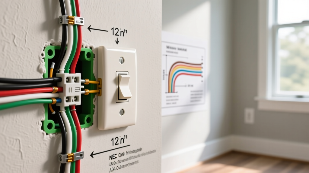
- Remove the Faceplate and Yoke: Unscrew the center 6-32 mounting screw. Gently pull the receptacle yoke out of the junction box. Do not disconnect any wires yet.
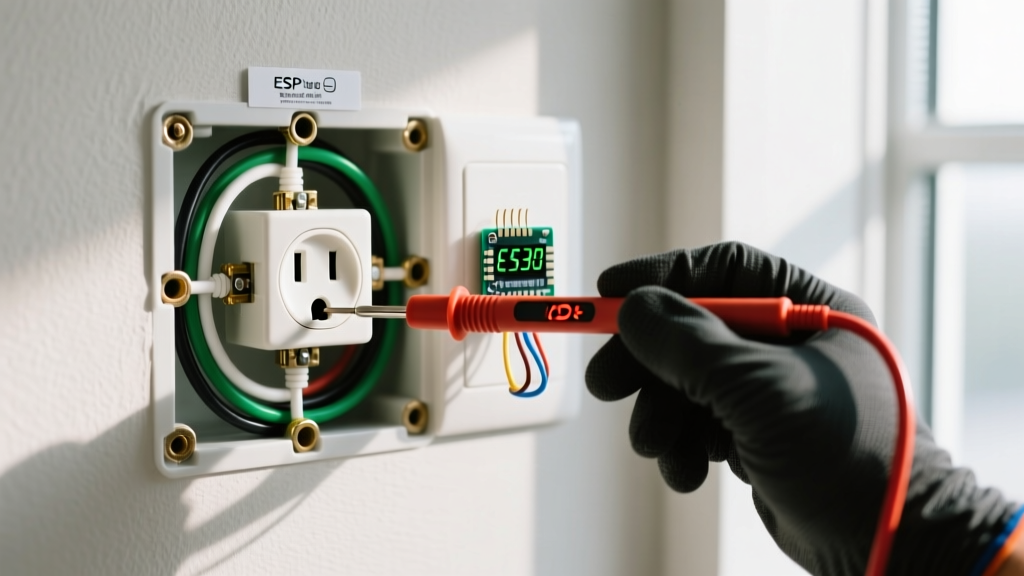
- Terminal-Level Verification: Using your Fluke 117, test from the brass (hot) screw to the bare copper ground, then from the brass screw to the silver (neutral) screw. Both must read 0.00V. Test the multimeter on a known live source immediately after to prove the meter's fuse and leads are intact.
- Identify Line vs. Load: Look at the back of the receptacle. The wires entering the box from the breaker panel are the Line. The wires continuing to the next outlet are the Load. If there is only one set of wires (1 black, 1 white, 1 bare), it is an endpoint.
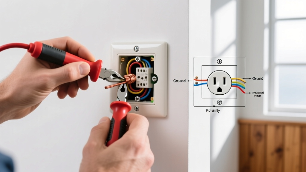
- Disconnect and Cap the Load: Loosen the terminal screws (or release the backstab holes) for the Load wires only. Immediately cap the Load black and Load white wires with Wago 221-412 connectors. This isolates the downstream circuit, allowing you to test the receptacle and the upstream wiring independently.
Isolation Matrix: Diagnosing the Disconnected Outlet
Once the Load wires are disconnected and capped, and power is restored to the panel, use this diagnostic matrix to interpret your findings.
| Symptom at Disconnected Outlet | Status of Downstream Outlets | Probable Fault Location | Next Diagnostic Step |
|---|---|---|---|
| Receptacle reads 120V; GFCI resets successfully. | Downstream outlets remain dead. | Fault is in the Load wiring or the next downstream junction. | Move to the next outlet in the chain and repeat the isolation process. |
| Receptacle reads 0V or trips breaker instantly. | N/A (Breaker won't hold). | Short circuit in upstream Line wiring or failed receptacle internal bus. | Disconnect Line wires, cap them, and test breaker. If breaker holds, receptacle is internally shorted. |
| Receptacle reads 40V-80V (Phantom Voltage). | Downstream outlets also read phantom voltage. | Open neutral (broken white wire) upstream in the daisy chain. | Locate the previous junction box; check for failed backstab neutral connections. |
Advanced Edge Cases: MWBC and Backstab Failures
The Multi-Wire Branch Circuit (MWBC) Hazard
If you pull the receptacle out and see two black wires and two red wires connected to the brass screws (with the metal break-off tab removed), you are dealing with a MWBC. This setup shares a single neutral wire between two 120V hot legs on opposite phases.
Critical Warning: According to the National Fire Protection Association (NFPA) and NEC Article 210.4, MWBCs must have a simultaneous disconnect (handle-tied breakers). If you only turn off one breaker, the shared neutral can carry the return current of the live leg, creating a lethal shock hazard at the disconnected neutral pigtail. Always verify both legs are dead before disconnecting any MWBC receptacle.
Backstabbed Push-In Terminals
Cheaper builder-grade receptacles (like older Leviton T5262 models) utilize push-in backstab connections rather than screw terminals. These are notorious for causing intermittent open-neutral faults due to thermal cycling. The internal brass spring grips loosen over years of heating and cooling, eventually arcing and failing. When troubleshooting a dead downstream circuit, wiggling the wires on a backstabbed outlet before full disconnection can temporarily restore continuity, instantly confirming the backstab as the failure point. Always replace backstabbed terminations with side-wiring (screw terminals) or pigtailing during repairs.
GFCI Load Terminal Isolation
When troubleshooting a GFCI receptacle (e.g., Leviton GFNT1-1W) that refuses to reset, the fault is frequently downstream, not in the GFCI itself. GFCIs monitor the current differential between Line and Load. If a downstream outdoor receptacle has water ingress or a crushed cable, the GFCI will trip to protect the circuit.
To diagnose this, disconnect the Load wires from the GFCI. Cap them safely. Reset the GFCI. If it holds and provides 120V at the Line terminals, the GFCI is perfectly healthy, and your fault lies in the Load wiring or the next receptacle in the chain. This simple isolation step saves countless homeowners from needlessly replacing expensive GFCI units.
Code-Compliant Reconnection (NEC 110.14(D))
Once the fault is diagnosed and repaired, reconnection must meet current electrical codes. The Electrical Safety Foundation International (ESFI) heavily emphasizes proper termination to prevent residential fires.
Under NEC 110.14(D), covered equipment terminations must be torqued to the manufacturer's specifications. For standard 15A and 20A commercial and residential receptacles (Hubbell, Leviton, Pass & Seymour), this specification is almost universally 14 in-lbs for 14 AWG and 12 AWG copper wire. Using your Milwaukee torque screwdriver ensures the wire won't vibrate loose or suffer from thermal creep, which causes high-resistance faults and arc flashes years down the line.
Final Troubleshooting Verification
After reconnection and applying torque:
- Verify the ground wire is securely terminated to the green screw and the metal box (if applicable).
- Ensure no bare copper is exposed outside the terminal saddle.
- Restore power and use a standard 3-prong receptacle tester to confirm correct wiring (two yellow lights on a standard Gardner Bender tester).
- Test GFCI/AFCI trip functions mechanically using the test button to ensure the internal solenoid is responsive.