
The Diagnostic Arsenal: Choosing the Right Tester
Understanding how to test electrical outlet circuits is a foundational skill for any DIYer, homeowner, or apprentice electrician. According to the U.S. Consumer Product Safety Commission (CPSC), electrical receptacles are involved in thousands of home fires and severe shock incidents annually. Faulty wiring, degraded connections, and improper grounding are invisible threats that only manifest when a high-draw appliance is plugged in or a ground fault occurs.
To properly diagnose a 120V standard NEMA 5-15R receptacle, you cannot rely on a single tool. A comprehensive testing strategy requires a tiered approach, moving from non-contact safety verification to precise voltage measurement. Below is a comparison matrix of the essential tools required for modern outlet diagnostics in 2026.
| Tool Category | Primary Function | 2026 Top Model Recommendation | Avg. Price Range |
|---|---|---|---|
| Non-Contact Voltage Tester (NCVT) | Verifying presence of AC voltage without touching bare wire | Klein Tools NCVT-2 (Dual-Range) | $25 - $35 |
| Plug-In Receptacle Tester | Quick fault detection (polarity, open ground, GFCI/AFCI trip) | Klein Tools RT250 (GFCI/AFCI) | $35 - $45 |
| Digital Multimeter (DMM) | Precision voltage measurement, continuity, and load testing | Fluke 117 True-RMS Electricians DMM | $190 - $220 |
Phase 1: Safety Verification with a Non-Contact Voltage Tester
Before inserting any pronged tester or removing the receptacle cover plate, you must verify the energized state of the circuit. The National Fire Protection Association (NFPA) mandates treating all circuits as live until proven otherwise.
Insert the tip of a dual-range NCVT (like the Klein NCVT-2) directly into the shorter (hot) slot of the outlet. A dual-range model is critical because it detects both standard line voltage (70-1000V AC) and low-voltage control wires (12-48V AC), preventing false negatives caused by shielded cables or deep-set terminals.
Expert Warning: NCVTs detect electromagnetic fields, not direct electrical contact. They can yield false positives due to capacitive coupling (ghost voltage) from adjacent live wires in the same wall cavity. Always confirm an NCVT's functionality on a known live source before and after testing your target outlet.
Phase 2: Quick Fault Detection with a Receptacle Tester
Once safety is established, plug in a modern receptacle tester. Older, basic three-light testers are largely obsolete for modern homes equipped with AFCI (Arc-Fault Circuit Interrupter) and dual-function breakers. We recommend the Klein Tools RT250, which features a microprocessor-controlled solenoid.
Why the Solenoid Matters for AFCI/GFCI Testing
Cheap testers use a simple resistor to create a ground fault, which often fails to trip modern electronic GFCI receptacles or inadvertently trips upstream AFCI breakers due to the electrical noise generated during the test. The RT250 uses a precise solenoid pulse that simulates a true 6mA ground fault, tripping the GFCI mechanism cleanly without nuisance-tripping the arc-fault logic at the main panel.
- Correct Wiring: Two yellow lights illuminate.
- Open Ground: Center yellow light only. (Common in pre-1960s knob-and-tube retrofits).
- Reverse Polarity: Left and right lights illuminate. (The hot and neutral wires are swapped—a severe shock hazard).
- Hot/Ground Reverse: Right yellow and red lights. (Indicates a missing neutral and a bootlegged ground).
Phase 3: Precision Diagnostics with a Digital Multimeter
While a receptacle tester provides a quick pass/fail, it cannot tell you the quality of the circuit, the exact voltage drop, or the integrity of the neutral bond. For this, a True-RMS Digital Multimeter (DMM) with a Low Impedance (LoZ) mode, such as the Fluke 117, is mandatory.
Understanding ANSI C84.1 Voltage Tolerances
In North America, nominal household voltage is 120V. However, under the ANSI C84.1 standard, the acceptable utilization voltage range (Range A) is 114V to 126V. If your multimeter reads 108V at the receptacle under no load, you have a severe voltage drop issue caused by undersized wiring, a loose terminal at the breaker panel, or an overloaded shared neutral.
The 3-Point Voltage Test Procedure
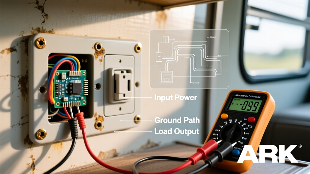
Set your DMM to AC Voltage (V~). Insert the black probe into the COM jack and the red probe into the V/Ω jack. Perform these three measurements:
- Hot to Neutral (Short slot to Wide slot): Should read 114V - 126V. This confirms the primary circuit path.
- Hot to Ground (Short slot to U-shaped ground): Should read 114V - 126V. This confirms the equipment grounding conductor is bonded back to the panel.
- Neutral to Ground (Wide slot to U-shaped ground): Should read less than 2.0V (ideally under 0.5V). This measures the voltage drop on the neutral wire. A reading above 2V indicates a loose neutral connection or an overloaded circuit.
Advanced Troubleshooting: Catching the 'Bootleg Ground'
One of the most dangerous edge cases in residential wiring is the "bootleg ground." This occurs when an unscrupulous handyman upgrades a 2-prong outlet to a 3-prong outlet by installing a jumper wire between the neutral silver terminal and the green ground screw. A standard 3-light receptacle tester will read "Correct" because it completes the circuit from Hot to Ground (which is artificially tied to Neutral).
How to Expose a Bootleg Ground
To catch this code violation, you must use your DMM and a high-draw load (like a 1500W hair dryer or space heater).
- Measure Hot-to-Ground. It will read ~120V.
- Measure Neutral-to-Ground. It will read exactly 0.0V.
- Plug your high-draw load into an adjacent outlet on the same circuit and turn it on.
- Re-measure Neutral-to-Ground. If the voltage rises to 1.5V - 4.0V while the load is running, you have a bootleg ground. The current is flowing back through the neutral wire, and because the ground is jumpered to it, the ground wire is now carrying return current—a massive shock and fire hazard.
Eliminating Ghost Voltages with LoZ Mode
When testing older homes or multi-gang switch boxes, you may encounter "ghost voltages." This happens when an unenergized wire runs parallel to a live wire for a long distance, picking up an induced AC voltage via capacitive coupling. A standard high-impedance DMM might read 40V to 80V on a dead wire, leading you to believe the circuit is still live.
Switch your Fluke 117 (or equivalent True-RMS meter) to LoZ (Low Impedance) mode. This inserts a low-impedance load into the meter's input circuit, effectively bleeding off the capacitively coupled ghost voltage and dropping the reading to a true 0.0V, confirming the wire is safely de-energized.
Summary of Material Requirements
Testing electrical outlets is not merely about checking if a lamp turns on; it is about verifying the integrity of the life-safety grounding path and the stability of the voltage delivery. By utilizing a tiered tool approach—starting with an NCVT for safety, moving to a solenoid-based receptacle tester for fault mapping, and finishing with a True-RMS DMM for precision voltage analysis—you ensure your home's electrical infrastructure meets modern safety codes and operates reliably under load.