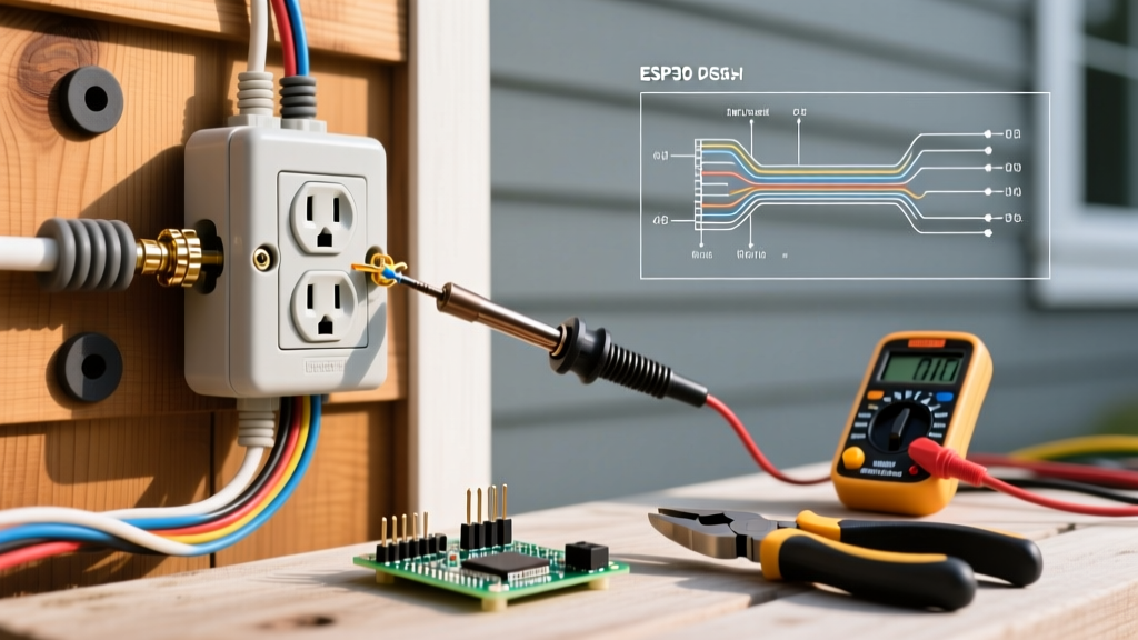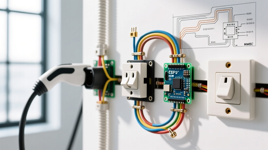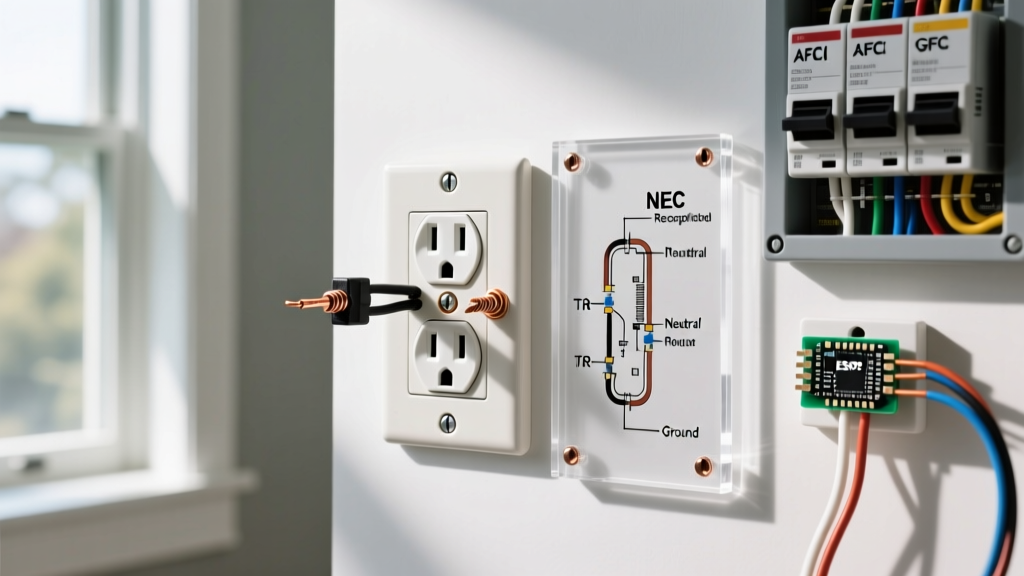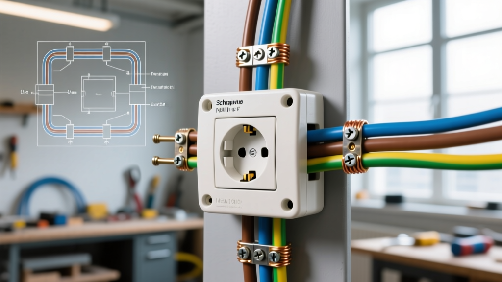

Understanding the Electrical Outlet Hidden Camera Architecture
Integrating surveillance into existing home infrastructure has evolved significantly. As of 2026, the modern electrical outlet hidden camera is no longer just a novelty plug-in device; it is a sophisticated, hardwired security node. For DIY electronics enthusiasts and licensed electricians alike, understanding the internal wiring diagrams, power delivery requirements, and thermal dynamics of these devices is critical for a safe, code-compliant installation.
Unlike battery-powered or standard USB-powered spy cameras, a hardwired outlet-integrated camera taps directly into the 120V AC branch circuit. It utilizes an internal or pigtailed AC-to-DC buck converter to step down the mains voltage to a safe 5V DC (typically drawing between 1A and 2A) to power the image sensor, Wi-Fi SoC (System on Chip), and local microSD storage. This guide serves as a comprehensive wiring diagram reference for installing these modules behind standard NEMA 5-15R receptacles.
Wiring Diagram Reference: Hardwired In-Wall Module
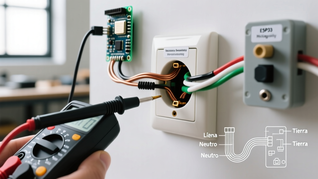
When installing a DIY hidden camera module (such as the popular Tuya-based 4K HD1080P in-wall modules or Spy-Max AC-to-DC kits) behind a standard duplex receptacle, you are essentially creating a parallel tap on the branch circuit. Below is the text-based schematic reference for the wiring topology.
Schematic Topology
- Line (Hot / Black Wire): Connects to the brass screw on the receptacle AND splices (via wire nut or Wago 221-412) to the AC Input (L) on the camera's power module.
- Neutral (White Wire): Connects to the silver screw on the receptacle AND splices to the AC Input (N) on the camera's power module.
- Ground (Bare/Green Wire): Connects exclusively to the green grounding screw on the receptacle and the metal junction box (if applicable). Note: Most Class 2 double-insulated camera modules do not require an earth ground connection for the low-voltage DC side.
- DC Output (5V): The camera module's integrated micro-USB or barrel jack plugs directly into the camera PCB, which is typically mounted to the back of the receptacle yoke or secured inside the junction box cavity.
Safety Warning: Never connect the 120V AC mains directly to the camera's DC input pins. Doing so will result in catastrophic component failure, arcing, and a severe fire hazard. Always verify the presence of an integrated AC-DC step-down module rated for 100-240V AC input.
NEC Code Compliance & Box Fill Calculations
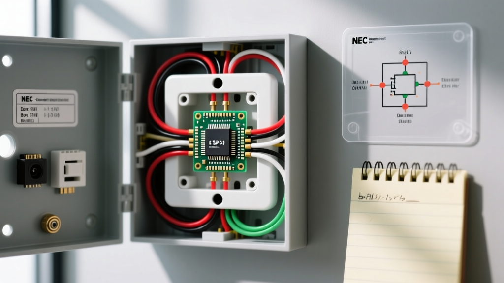
The most common point of failure—and code violation—when installing an electrical outlet hidden camera is ignoring junction box fill capacity. The NFPA 70 National Electrical Code (NEC) strictly governs how many conductors and devices can safely occupy a single-gang box to prevent heat buildup and wire crushing.
Calculating Box Fill for Camera Installations
According to NEC Article 314.16, box fill is calculated based on the largest conductor entering the box. For standard 14 AWG copper wire (15A circuits), each conductor counts as 2.0 cubic inches.
| Component | Quantity | Volume Multiplier (14 AWG) | Total Cubic Inches |
|---|---|---|---|
| Hot & Neutral Conductors (Entering/Leaving) | 4 | 2.0 cu in each | 8.0 cu in |
| Grounding Conductors (All combined) | 1 | 2.0 cu in | 2.0 cu in |
| Receptacle Device (Yoke) | 1 | 2 x 2.0 cu in | 4.0 cu in |
| Hidden Camera Module & Pigtails | 1 | Equivalent to 1 device/clamp | 4.0 cu in |
| Total Minimum Required Volume | Standard 18 cu in box is INSUFFICIENT | 18.0+ cu in | |
Expert Recommendation: Always upgrade to a deep single-gang box, such as the Carlon E989ARL (23 cubic inches) or a 28-cubic-inch adjustable metal box, to accommodate the physical bulk of the camera's PCB, the AC-DC transformer, and the necessary wire bend radiuses. For deeper technical guidance on residential wiring safety, refer to the Electrical Safety Foundation International (ESFI) guidelines on junction box overcrowding.
Component Comparison Matrix: Hardwired vs. Pass-Through
Not all electrical outlet hidden cameras are created equal. When planning your wiring diagram, you must choose between a hardwired in-wall module and a pass-through plug-in receptacle.
| Feature | Hardwired In-Wall DIY Module | Pass-Through Plug-In Receptacle |
|---|---|---|
| Installation Type | Requires junction box wiring & splicing | Plugs into existing outlet (No wiring) |
| Concealment Level | ||
| Continuous Power | Yes (Unswitched branch circuit) | Yes (Unless plugged into a switched outlet) |
| Thermal Dissipation | Poor (Trapped in wall cavity) | Excellent (Exposed to room air) |
| Wi-Fi Signal Penetration | Attenuated by drywall/metal boxes | Strong (External antenna placement) |
| Average Cost (2026) | $45 - $85 (Tuya/Spy-Max kits) | $90 - $150 (Proprietary brands) |
Step-by-Step Installation & Wiring Procedure
- De-energize the Circuit: Turn off the 15A or 20A breaker at the main panel. Verify zero voltage using a non-contact voltage tester (NCVT) and a multimeter at the receptacle terminals.
- Extract and Upgrade the Box (If Necessary): Remove the existing receptacle. If the current box is a standard 14-cubic-inch shallow box, cut the drywall carefully and install an old-work deep box (e.g., Carlon B618R-UPC) to ensure adequate box fill volume.
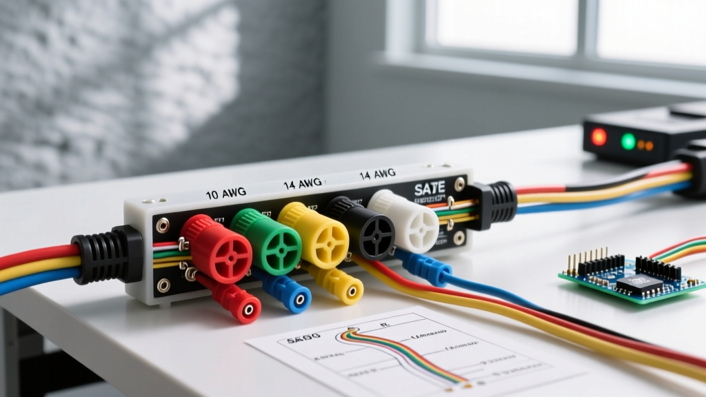
- Prepare the Pigtails: Strip 3/4 inch of insulation from 14 AWG THHN stranded wire. Use Wago 221-412 lever nuts to splice the Line (Black) and Neutral (White) from the wall to both the receptacle and the camera's AC-DC step-down module. This maintains circuit continuity for downstream outlets.
- Mount the Camera Module: Secure the camera PCB to the back of the receptacle yoke using double-sided VHB tape or the provided M3 nylon standoffs. Ensure the camera lens aligns perfectly with the custom-cut hole in the wall plate.
- Manage the Antenna: If your module features an external 2.4GHz Wi-Fi antenna, route it flat against the side of the plastic junction box. Never leave the antenna coiled behind the metal yoke, as this will cause severe signal degradation.
- Test and Close: Restore power at the breaker. Use your smartphone to connect to the camera's local AP, configure the Wi-Fi credentials, and verify the live feed before pushing the assembly into the wall and tightening the wall plate.
Critical Failure Modes & Troubleshooting
Even with a perfect wiring diagram, environmental and electrical factors can cause an electrical outlet hidden camera to malfunction. Here are the most common edge cases encountered in the field:
1. Thermal Throttling and Shutdown
Hidden cameras generate significant heat. A 5V 2A module dissipates roughly 3 to 5 watts of thermal energy. Inside a sealed wall cavity insulated with fiberglass or spray foam, ambient temperatures can easily exceed 50°C (122°F). When the internal SoC reaches its thermal limit (usually around 75°C), the device will drop frames, disconnect from Wi-Fi, or shut down entirely. Solution: Install thermal pads between the camera's voltage regulator and the metal junction box (if using a metal box) to use the box as a passive heatsink.
2. RF Shielding by Metal Junction Boxes
If you are wiring this camera into an older home with steel single-gang boxes, the metal acts as a Faraday cage, blocking the 2.4GHz Wi-Fi signal required for remote viewing. Solution: Swap the metal box for a PVC/fiberglass old-work box, or use a camera module that supports an external SMA antenna routed through the drywall into the room cavity.
3. Voltage Drop and Brownouts
If the camera is installed at the far end of a long 14 AWG branch circuit heavily loaded with other devices (like vacuums or space heaters), momentary voltage sags can cause the camera's internal DC-DC converter to brownout, corrupting the microSD card file system. Solution: Ensure the camera module features a dedicated supercapacitor or a high-quality LC filter on the 5V DC input rail to handle transient voltage dips.
Legal & Privacy Considerations
Wiring a hidden camera into a permanent electrical fixture crosses the line from temporary surveillance to fixed structural monitoring. It is imperative to understand the legal boundaries of deploying an electrical outlet hidden camera. According to the Electronic Frontier Foundation (EFF) and federal wiretapping laws, recording audio without the consent of at least one party (or all parties, depending on your state's two-party consent laws) is a severe criminal offense. Furthermore, placing hidden cameras in areas where individuals have a reasonable expectation of privacy (bathrooms, guest bedrooms, changing areas) is strictly illegal and carries heavy felony penalties. Always restrict the deployment of these devices to common areas, entryways, or your own private office spaces, and ensure proper signage or disclosure is provided to guests and contractors where legally mandated.
Summary
Successfully integrating an electrical outlet hidden camera requires more than just matching black to black and white to white. It demands a rigorous adherence to NEC box fill calculations, an understanding of RF attenuation in building materials, and proactive thermal management. By following the wiring diagram references and troubleshooting protocols outlined above, DIYers and professionals can deploy reliable, continuous-power surveillance nodes that operate safely within the parameters of modern residential electrical systems.