
Beyond the Schematic: Executing Your Wiring an Electrical Outlet Diagram
Staring at a wiring an electrical outlet diagram is the easy part; translating those 2D lines and symbols into a safe, code-compliant physical connection is where the real work begins. Whether you are wiring a standard 15-amp duplex receptacle or daisy-chaining multiple outlets on a single branch circuit, the schematic only provides the logic. To execute that logic flawlessly, you need a highly specific arsenal of tools and materials. In 2026, with stricter enforcement of the National Electrical Code (NEC) regarding torque specifications and tamper resistance, using the right gear is no longer optional—it is a legal and safety imperative.
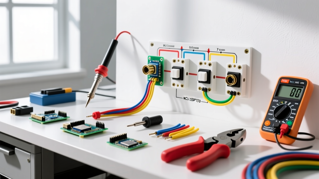
This guide bridges the gap between theory and practice. We will break down the exact tools, diagnostic equipment, and materials you need to bring your wiring an electrical outlet diagram to life, complete with specific model numbers, current market pricing, and expert application techniques.
Phase 1: Diagnostic & Safety Tools (Pre-Diagram Execution)
Before you strip a single wire or consult your diagram, you must verify the circuit state. Relying solely on a breaker panel label is a common failure mode that leads to severe injury.
- Non-Contact Voltage Tester (NCVT): The Klein Tools NCVT-41 (approx. $22) is a dual-range tester that detects both standard (70-1000V) and low voltage. Use this to confirm the outlet is dead before removing the faceplate.
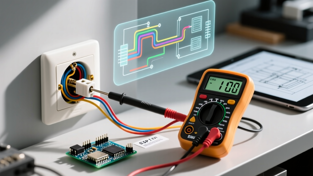
- True-RMS Digital Multimeter: For verifying neutral-to-ground bonds and checking for phantom voltages. The Fluke 117 True-RMS Multimeter (approx. $215) is the professional standard, though the AstroAI DM6000AR (approx. $35) is sufficient for basic DIY diagram verification.
- Receptacle Tester: The Gardner Bender GRT-501 (approx. $12) instantly reads open grounds, reversed polarity, and open neutrals. This is your post-wiring verification tool to ensure your physical build matches the diagram.
Phase 2: Core Hand Tools for Diagram Implementation
When your wiring an electrical outlet diagram calls for stripping 14 AWG solid copper and forming J-hooks, precision matters. Damaged wire insulation or nicked copper conductors create high-resistance hot spots that can lead to thermal failure inside the wall cavity.
Wire Strippers & Lineman Pliers
Forget the cheap multi-tool strippers that crush soft copper. You need dedicated, gauge-specific tools.
- Klein Tools 11063W Katapult Wire Stripper: Priced around $28, this tool features a shear-type cutting blade and precise stripping holes for 10-14 AWG solid wire. It removes insulation without scoring the copper, which is critical for maintaining the wire's ampacity rating.
- Klein Tools 200048EINS Lineman's Pliers: At $32, these feature a high-leverage design and a built-in crimping die. You will use the nose of these pliers to bend perfect 180-degree J-hooks on your solid copper wires, ensuring they wrap clockwise around the terminal screws exactly as implied by standard wiring diagrams.
Insulated Screwdrivers & Torque Drivers
A major update in recent NEC cycles (specifically Article 110.14(D)) mandates that electrical connections must be torqued to the manufacturer's specified values. Hand-tightening terminal screws by "feel" is now a code violation in many jurisdictions.
- Insulated Screwdrivers: The Wiha 32095 11-Piece Insulated Set (approx. $45) provides 1000V-rated protection. You will primarily use the #2 Phillips and 1/4-inch slotted tips for brass (hot) and silver (neutral) terminal screws.
- Torque Screwdriver: The Klein Tools 70900 Torque Screwdriver (approx. $135) is an investment, but it ensures you hit the exact 12 to 14 inch-pound specification required by most modern Leviton and Hubbell receptacles. This prevents both loose connections (arcing) and over-tightened connections (stripped threads or crushed wire).
Phase 3: Materials Mapping to Your Diagram Nodes
Your wiring an electrical outlet diagram will feature specific nodes: the receptacle itself, the grounding pigtail, and the wire connectors. Here is what you should be purchasing in 2026 to meet current safety standards.
| Diagram Node | Recommended Product (Model) | Approx. Cost | Why It Matters (NEC/Safety) |
|---|---|---|---|
| Receptacle | Leviton T5262-W (15A Tamper-Resistant) | $3.50 / ea | NEC 406.12 mandates TR receptacles in all dwelling unit areas to prevent child insertion injuries. |
| Wire Connectors | Wago 221-413 Lever-Nuts (3-Port) | $0.65 / ea | Superior to twist-on nuts for pigtailing; provides a visually verifiable, high-clamp-force connection. |
| Grounding Pigtail | 12 AWG Bare Solid Copper (Cut to 6") | $0.20 / ft | NEC 250.148 requires a dedicated equipment grounding conductor connection to the metal box and receptacle. |
| Cable Sheathing | Southwire 14/2 or 12/2 NM-B Romex | $0.75 / ft | Ensure the gauge matches the breaker (15A=14AWG, 20A=12AWG). Never mix 14AWG wire on a 20A circuit. |
Translating Diagram Symbols to Physical Connections
When you look at a standard wiring an electrical outlet diagram, you will see lines representing the hot (black), neutral (white), and ground (bare/green) wires. Here is how to physically execute those specific diagram nodes using the tools listed above.
1. The Grounding Pigtail Node
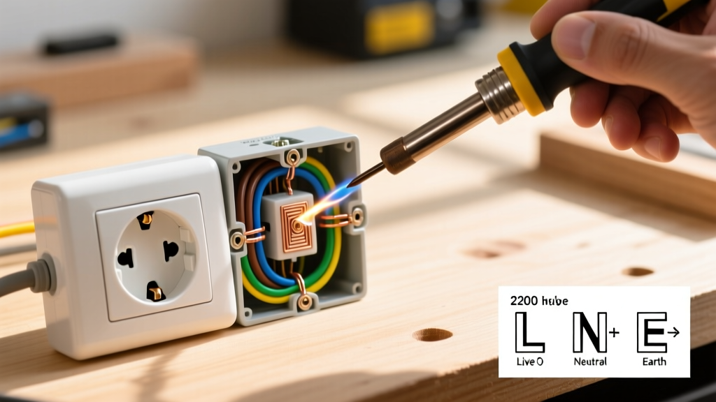
Most diagrams show the bare ground wire splitting: one path to the metal junction box, one to the green grounding screw on the receptacle. Execution: Strip the incoming ground wire. Use a Wago 221-413 Lever-Nut to join the incoming ground, the box grounding clip (or screw), and your 6-inch 12 AWG bare copper pigtail. Form a tight J-hook on the pigtail using your Klein Lineman's pliers and secure it under the green terminal screw. Torque to 12 in-lbs.
2. The Neutral (White) Bus Node
Diagrams show the white wire connecting exclusively to the silver screws. Execution: Strip exactly 3/4 inch of insulation using the 14 AWG hole on the Klein Katapult stripper. If you are daisy-chaining (feeding power to the next outlet), do not use the "backstab" push-in holes on the back of the receptacle. Backstab connections rely on a small spring-metal tang that frequently loses tension over years of thermal expansion and contraction, leading to open-neutral failures. Always use the side terminal screws and torque them down.
3. The Hot (Black) Line Node
The black wire connects to the brass screws. Execution: Identify the "Line" vs. "Load" if you are working from a GFCI diagram. For standard outlets, polarity on the brass screws does not strictly matter if there is only one cable, but maintaining consistency (e.g., incoming line on the top brass screw, outgoing load on the bottom) makes future troubleshooting significantly easier.
Expert Edge Cases & 2026 NEC Compliance
Standard diagrams rarely account for the messy reality of older homes or complex modern circuits. Here are two edge cases you must be prepared for:
Multi-Wire Branch Circuits (MWBC)
If you open a junction box and find two hot wires (one black, one red) sharing a single neutral (white) wire, you are looking at an MWBC. Your standard wiring an electrical outlet diagram will not apply here. Crucial Safety Step: You must identify and turn off the double-pole breaker. If you only turn off one pole, the shared neutral will still be carrying the return current from the other active pole, which can result in a lethal shock when you disconnect the neutral wire. Furthermore, NEC 210.4(B) requires a simultaneous disconnect (handle tie) for the breakers feeding this circuit.
Box Fill Calculations
Diagrams don't show physical space constraints. If you are adding pigtails, Wago lever-nuts, and a bulky TR receptacle into a standard shallow 14-cubic-inch plastic nail-on box, you will likely violate NEC Article 314.16 (Box Fill). The Fix: Count each wire, clamp, and device. A 14 AWG wire counts as 2.0 cubic inches. A receptacle counts as 4.0 cubic inches. If your math exceeds the box volume stamped on the back of the enclosure, you must upgrade to a deep 22-cubic-inch box (e.g., Carlon E989R-UPR, approx. $2.50) before proceeding.
Pro-Tip for 2026: Always leave at least 6 inches of free conductor length measured from the point in the box where it last emerges from its raceway or cable sheath, per NEC 300.14. If your diagram requires a complex pigtail setup and your wires are cut too short, do not attempt to splice extensions inside a crowded box; replace the cable run.
Final Verification
Once your physical wiring matches the logic of your wiring an electrical outlet diagram, push the wires neatly into the back of the box using a folding technique (accordion style, not a tight ball). Mount the receptacle, ensuring the yoke sits flush against the drywall or plaster ring. Restore power at the panel and insert your Gardner Bender GRT-501 receptacle tester. Two yellow lights indicate a correct, code-compliant connection. If you see a red light, kill the power immediately and re-verify your terminal connections against the schematic.
Authoritative References & Code Standards
To ensure your projects remain compliant and safe, always consult the latest codes and safety guidelines:
- National Fire Protection Association (NFPA) NEC Code 70 - The definitive source for all box fill, torque, and wiring method regulations.
- Electrical Safety Foundation International (ESFI) DIY Safety - Excellent resource for understanding the risks of MWBCs and backstabbed connections.
- U.S. Consumer Product Safety Commission (CPSC) Electrical Safety - Data on residential electrical fires caused by improper receptacle terminations.