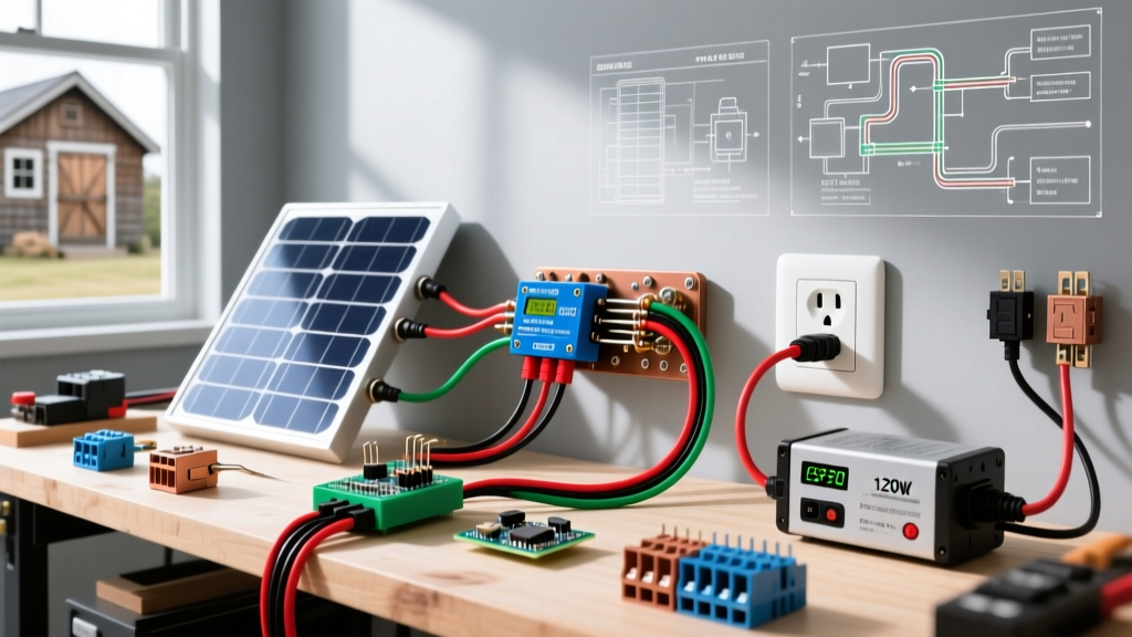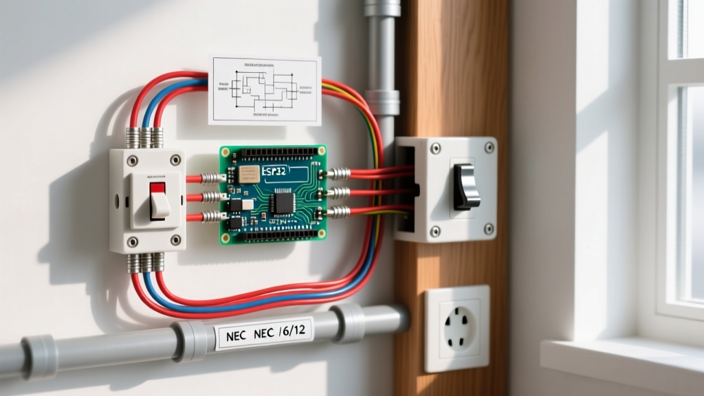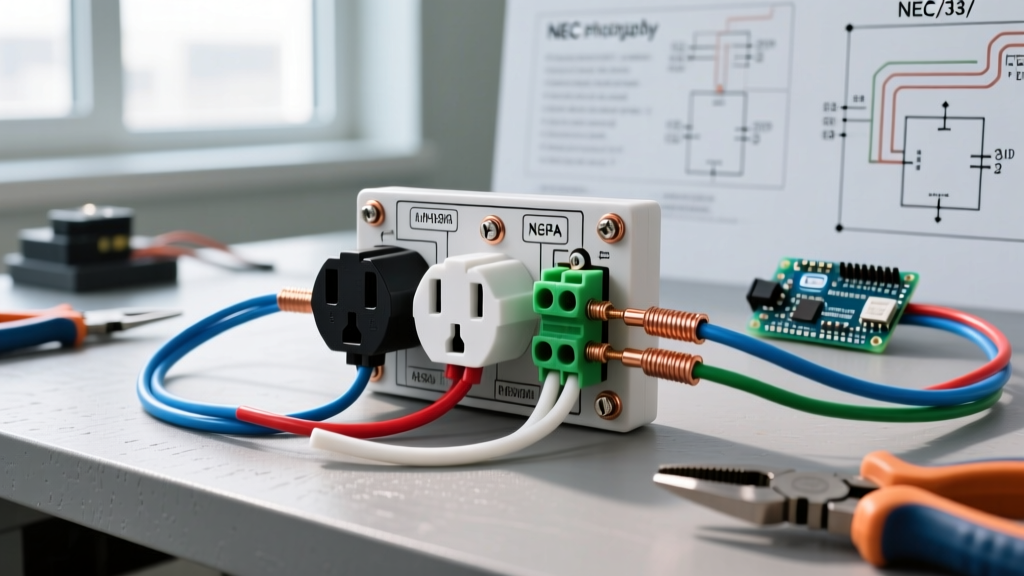

Understanding the Wiring Diagram for Dryer Plug Configurations
Installing a 240-volt appliance receptacle is one of the most common intermediate DIY electrical projects. However, interpreting the correct wiring diagram for dryer plug configurations requires a solid understanding of National Electrical Code (NEC) updates and terminal mapping. Unlike standard 120-volt, 15-amp household outlets, electric dryers demand a dedicated 30-amp, 240-volt circuit capable of handling continuous high-current loads for heating elements and 120-volt accessories like drum motors and control boards simultaneously.
As of the 2026 NEC cycle, the standards for grounding and neutral isolation remain strict. The National Fire Protection Association (NFPA) mandates specific separation of the neutral and ground paths to prevent chassis energization, a critical safety evolution that completely changed how modern dryer receptacles are wired compared to pre-1996 installations.
The Evolution: NEMA 10-30 (3-Prong) vs. NEMA 14-30 (4-Prong)
Before diving into the physical installation, you must identify which receptacle type your project requires. The transition from 3-prong to 4-prong outlets was driven by a fatal flaw in older wiring methods.
- NEMA 10-30R (3-Prong): This legacy configuration utilizes two hot wires and a combined neutral/ground wire. Because the neutral carries return current, the dryer's metal chassis could become energized if the neutral connection failed. While existing 3-prong setups are grandfathered in under NEC Article 250.140, new installations strictly prohibit NEMA 10-30 receptacles.
- NEMA 14-30R (4-Prong): The modern standard. It features two hot wires, a dedicated neutral, and a separate equipment grounding conductor. This ensures the chassis is never tied to a current-carrying conductor, drastically reducing shock hazards.
Wiring Diagram for Dryer Plug: 4-Prong NEMA 14-30R Breakdown
When reviewing a standard wiring diagram for a 4-prong dryer plug, you will be working with 10/3 AWG copper cable (typically NM-B Romex for dry indoor residential use, or MC cable if local codes require metal cladding). The cable contains four distinct conductors: Black (Hot), Red (Hot), White (Neutral), and Bare Copper (Ground).
| Receptacle Terminal | Screw Color | 10/3 Cable Wire Color | Dryer Cord Wire Color | Function |
|---|---|---|---|---|
| Top / Bottom Straight Blades | Brass / Dark | Black & Red | Black & Red | 120V/240V Hot Legs (Line 1 & Line 2) |
| Bottom Angled Blade (L-Shape) | Silver / White | White | White | Dedicated Neutral (Return Path for 120V) |
| Top Rounded Pin | Green | Bare Copper | Green | Equipment Grounding Conductor (Safety) |
Step-by-Step 4-Prong Dryer Receptacle Installation
Follow this precise workflow to ensure a safe, code-compliant installation. Always verify local permitting requirements before beginning work on high-voltage circuits.
Phase 1: Preparation and Safety Lockout
CRITICAL SAFETY WARNING: Never assume a breaker is off just because the switch is flipped. Use a reliable non-contact voltage tester (such as the Milwaukee 2201-20 or Klein Tools NCVT-2) to verify zero voltage at the panel and the receptacle box before touching any conductors. According to the Electrical Safety Foundation International (ESFI), failure to verify de-energized circuits is a leading cause of residential electrocution.
Gather your tools: a heavy-duty wire stripper (Klein Tools 11055), a torque screwdriver, a 3/8-inch nut driver, and your NEMA 14-30R receptacle (e.g., Leviton 278-S00 or Bryant 9430FR, typically costing between $15 and $25 in 2026).
Phase 2: Panel Termination (The Source)
Run your 10/3 NM-B cable from the main panel to the receptacle location. At the main service panel:
- Land the Bare Copper wire on the dedicated grounding bus bar.
- Land the White wire on the isolated neutral bus bar. (Note: In a main panel, neutral and ground bars are bonded. If you are running this from a subpanel, they must remain strictly isolated).
- Connect the Black and Red wires to a new 30-Amp, 240-Volt double-pole breaker (e.g., Square D HOM230CP or Siemens Q230). Ensure the breaker is fully seated on both hot bus stabs.
Phase 3: Terminating the Receptacle
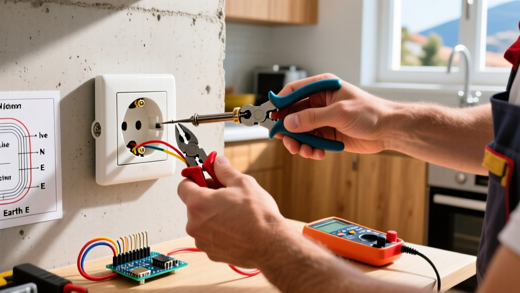
At the outlet box, strip the outer NM-B jacket back about 8 inches, and strip exactly 3/4 inch of insulation from the individual conductors. Form a clockwise hook on the end of each wire so that tightening the screw pulls the loop closed rather than pushing it out.
- Ground: Attach the bare copper to the green grounding screw on the receptacle strap.
- Neutral: Attach the white wire to the silver terminal (usually marked with a 'W' or 'N').
- Hots: Attach the black and red wires to the two brass/dark terminals. Polarity between the two hot legs does not matter for a dryer.
Pro-Tip: Use a torque screwdriver set to the manufacturer's specification (typically 35 to 40 in-lbs for 10 AWG wire). Under-torqued terminal screws cause high-resistance connections, leading to heat buildup and melted receptacles over time.
The 3-Prong to 4-Prong Dryer Cord Conversion
A common scenario for beginners is moving an older dryer with a 3-prong cord into a new home with a 4-prong NEMA 14-30R receptacle. You must replace the cord, but more importantly, you must alter the dryer's internal bonding.
On a 3-prong setup, the dryer has a copper bonding jumper (strap or wire) connecting the center neutral terminal to the metal chassis ground. When upgrading to a 4-prong cord (like the Utilitech Pro 4-Prong 30A cord, approx. $32), you must remove this bonding jumper. If you leave the jumper in place while using a 4-prong cord, you create a parallel neutral path, sending return current through the ground wire and the dryer's chassis—a severe shock hazard and an NEC violation.
Critical Troubleshooting & Edge Cases
Even with a perfect wiring diagram for your dryer plug, edge cases can cause operational failures. Here is how to diagnose them:
1. The Dryer Tumbles but Won't Heat
The drum motor runs on 120V (using one hot leg and the neutral), while the heating element requires the full 240V (using both hot legs). If the dryer tumbles but produces no heat, you likely have a tripped half of the double-pole breaker, or one of the hot wires (Black or Red) has backed out of its terminal. Turn off the breaker and re-torque the hot terminals.
2. The 'Bootleg Ground' Mistake
Some beginners, attempting to wire a 4-prong outlet using older 10/2 cable (which lacks a dedicated ground), will bridge the neutral terminal to the ground terminal using a jumper wire. Never do this. This is known as a bootleg ground. If the neutral wire breaks anywhere upstream, the entire metal chassis of the dryer will become energized with 120 volts. Always pull new 10/3 cable for a 4-prong setup.
3. Voltage Drop and Wire Sizing
If your laundry room is located more than 100 feet from the main electrical panel, standard 10 AWG wire may experience significant voltage drop under the heavy load of a heating element. For runs exceeding 100 feet, upgrade to 8 AWG copper wire to maintain efficiency and prevent the breaker from nuisance-tripping due to heat-induced resistance. Note that 8 AWG wire requires larger wire nuts and may need to be pigtailed down to 10 AWG to fit into the receptacle's terminal screws.
Frequently Asked Questions
Can I use a 50-amp breaker and 6 AWG wire for a 30-amp dryer outlet?
While oversizing wire is generally safe from a fire perspective, the NEC requires the receptacle rating to match the breaker rating. You cannot install a 30-amp NEMA 14-30R receptacle on a 50-amp breaker. If you pull 6 AWG wire, you must still use a 30-amp breaker to properly protect the appliance's internal wiring.
Does the white neutral wire need to be marked if used as a hot?
In a standard 240V/120V dryer circuit, the white wire is strictly used as a neutral and should not be taped black or red. It must remain white to clearly identify it as the grounded conductor to any future electrician working on the panel.