
Understanding the '4-Wire' Outlet Mystery
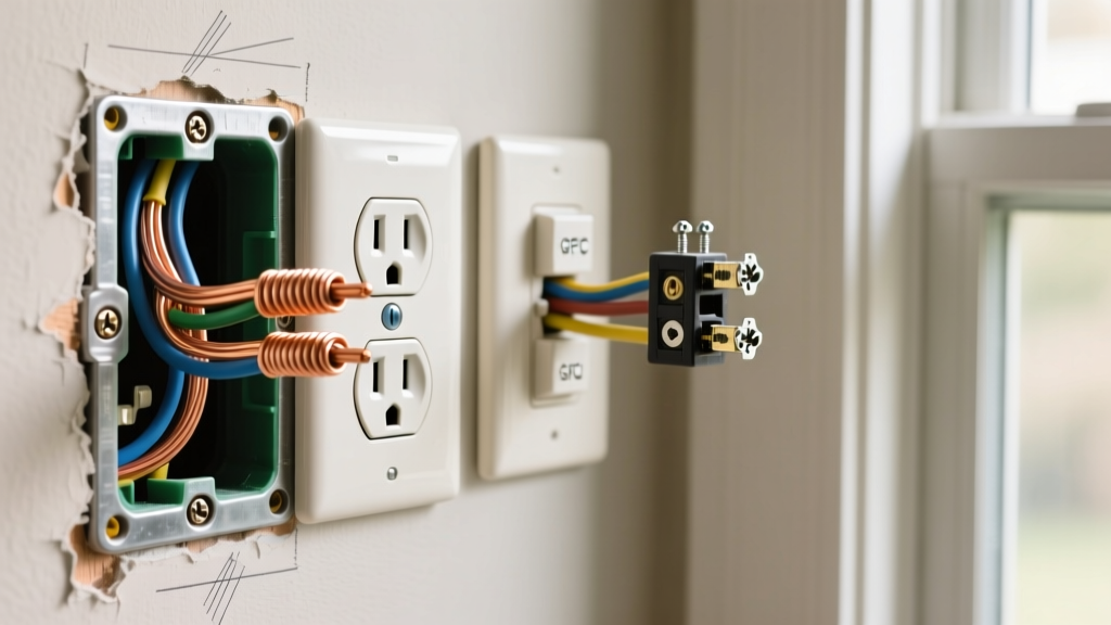
Opening a junction box to replace a standard duplex receptacle and finding four distinct insulated wires (plus a bare copper or green ground) is one of the most common points of confusion for DIYers. A standard 120V outlet only requires three connections: one hot, one neutral, and one ground. So, what are the extra wires doing, and how do you safely reconnect them?
When learning how to replace an electrical outlet with 4 wires, you are almost certainly dealing with one of two specific wiring scenarios: a daisy-chained run (Line and Load) or a Multi-Wire Branch Circuit (MWBC). Misidentifying these can lead to tripped breakers, melted terminals, or severe shock hazards. This wiring diagram reference will break down both scenarios, provide exact terminal mappings, and detail the modern code requirements for a safe installation.
Scenario 1: The Daisy-Chain (Line and Load)
The most common reason for four wires in a standard 15A or 20A residential outlet box is that the receptacle sits in the middle of a circuit run. It is receiving power from the breaker panel (Line) and passing power to the next outlet downstream (Load).
Wire Identification & Diagram Mapping
- 2 Black Wires (Hots): One brings power from the panel; the other carries power to the next outlet.
- 2 White Wires (Neutrals): One returns current to the panel; the other completes the circuit for the downstream outlet.
- 1 Bare/Green Wire (Ground): Safety ground (sometimes bundled with a pigtail, making it look like 5 wires total).
Wiring Diagram Reference (Daisy-Chain):
Black Wire 1 (Line) ➔ Brass Screw (Top)
Black Wire 2 (Load) ➔ Brass Screw (Bottom)
White Wire 1 (Line) ➔ Silver Screw (Top)
White Wire 2 (Load) ➔ Silver Screw (Bottom)
Ground ➔ Green Screw
The Pigtailing Alternative (Recommended for 2026 Standards)
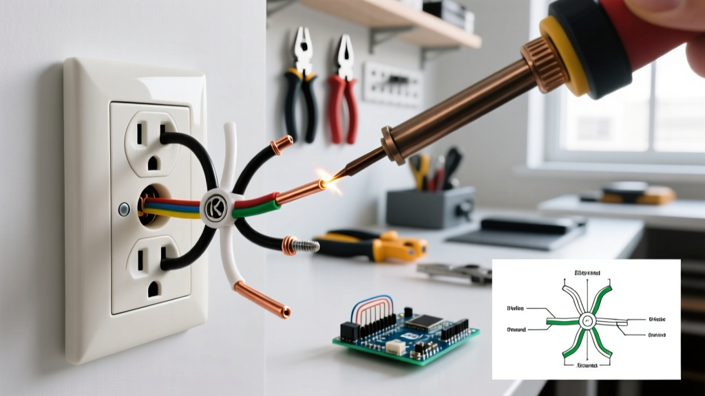
While modern receptacles like the Leviton T5262 (approx. $3.50) feature side-wiring clamps that allow two wires under one screw, many master electricians prefer 'pigtailing.' Pigtailing involves using a wire nut or lever connector to join the two black wires with a short 6-inch black jumper wire, which then connects to the single brass screw. The same is done for the white wires.
Pro-Tip: Ditch the standard twist-on wire nuts in tight boxes. Use WAGO 221 Lever-Nuts (rated for 32A / 600V). They require less physical space, provide a visual inspection window to ensure no bare copper is exposed, and eliminate the risk of a wire nut vibrating loose over time.
Scenario 2: Multi-Wire Branch Circuit (MWBC)
If your four wires consist of one black, one red, one white, and one ground, you are dealing with a Multi-Wire Branch Circuit. This setup uses two 120V hot wires sharing a single neutral wire to deliver 240V to the box, effectively acting as two separate circuits.
Critical Safety Warning: Handle Ties
According to the National Electrical Code (NEC) Article 210.4, all ungrounded (hot) conductors of an MWBC must be provided with a means to simultaneously disconnect them at the panel. This requires a handle-tie or a 2-pole breaker. If you turn off only one breaker to work on this outlet, the other hot wire remains live at 120V, posing a lethal shock hazard.
Wiring Diagram Reference (MWBC)
For an MWBC, the two hot wires must be connected to separate hot terminals, and the connecting brass fin must be broken off to prevent a dead short across the 240V potential.
- Red Wire (Hot A): Connect to one Brass Screw.
- Black Wire (Hot B): Connect to the other Brass Screw.
- Action Required: Use needle-nose pliers to snap off the small brass connecting tab between the two brass screws. Do NOT break the silver tab on the neutral side.
- White Wire (Shared Neutral): Connect to one Silver Screw. (If a downstream outlet requires a neutral, you must pigtail the white wire).
- Ground: Connect to the Green Screw.
Comparison Matrix: Daisy-Chain vs. MWBC
| Feature | Daisy-Chain (Line/Load) | Multi-Wire Branch Circuit (MWBC) |
|---|---|---|
| Wire Colors Present | 2 Black, 2 White, 1 Ground | 1 Black, 1 Red, 1 White, 1 Ground |
| Voltage Between Hots | 0V (Same phase) | 240V (Opposite phases) |
| Brass Tab (Hot Side) | Leave Intact | MUST Break Off |
| Silver Tab (Neutral) | Leave Intact | Leave Intact |
| Breaker Configuration | Single Pole (15A or 20A) | Two-Pole or Handle-Tied Singles |
Step-by-Step Replacement & Torque Specifications
Replacing the outlet is not just about matching colors; it is about ensuring mechanical integrity. The Occupational Safety and Health Administration (OSHA) and NEC 110.14(D) mandate specific torque values for electrical terminations to prevent arc faults and fires caused by loose connections.
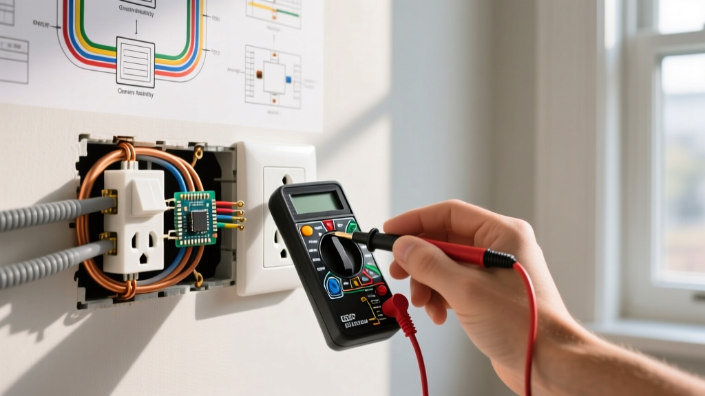
- Kill the Power & Verify: Turn off the breaker. Use a non-contact voltage tester like the Fluke 1AC-II ($35) to verify zero voltage on all wires. Test the tester on a known live circuit first to ensure the battery is functional.
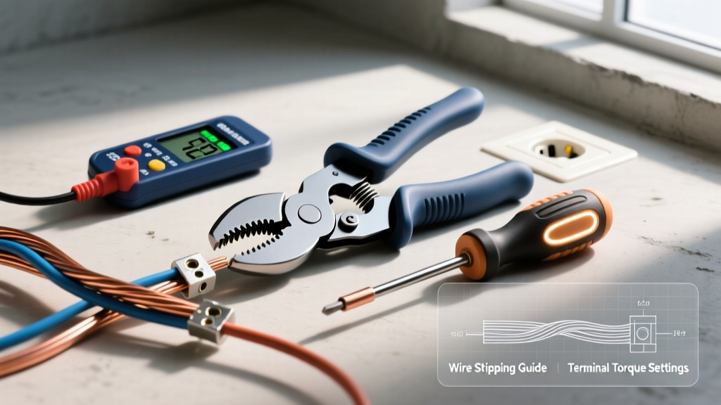
- Prepare the Wires: Strip exactly 3/4 inch of insulation using precision strippers (e.g., Klein Tools 11055). Do not nick the copper conductor, which creates a weak point that can snap under the screw head.
- Form the Shepherd's Hook: Bend the bare wire into a tight clockwise hook. The clockwise direction ensures that tightening the screw pulls the wire loop tighter, rather than pushing it out from under the terminal.
- Apply Correct Torque: Standard 15A and 20A receptacles (like the Eaton TR15A) generally require 14 in-lbs (1.58 Nm) of torque for 14-10 AWG wire. Use an insulated torque screwdriver, such as the Wiha 10109 ($65), to achieve exact tension. Hand-tightening often leads to under-torqued screws that heat up over time.
- Wrap with Electrical Tape: While not strictly required by code if the box is properly grounded and the wires are neatly folded, wrapping the sides of the receptacle with 3M Super 33+ vinyl tape prevents accidental shorting against the metal junction box edges when pushing the device back in.
Common Edge Cases & Troubleshooting
Downstream Outlets Are Dead After Replacement
If you replaced the outlet and the subsequent outlets in the room lost power, you likely failed to connect the 'Load' wires. Double-check your pigtails or ensure both the top and bottom screws are tightly secured. If you used the 'backstab' push-in holes on the back of the old outlet, note that many modern premium receptacles have eliminated these failure-prone connections entirely.
Reversed Polarity on Tester
If your $12 Klein Tools RT250 receptacle tester shows 'Open Ground' or 'Hot/Neutral Reversed', you have either connected the black wire to the silver screw, or the bare ground wire is not making solid contact with the green screw and the metal box. Always verify the ground continuity from the box to the panel.
GFCI Integration in a 4-Wire Box
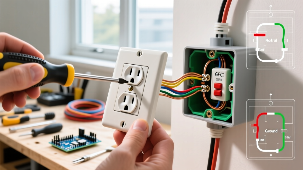
If you are upgrading a 4-wire daisy-chain box to a GFCI receptacle (required by the Consumer Product Safety Commission (CPSC) for kitchens, bathrooms, and garages), you must be meticulous about Line vs. Load. Connect the incoming power (Line) to the LINE terminals. Connect the outgoing power (Load) to the LOAD terminals. If you mix these up, the GFCI will not protect downstream outlets, and the 'Reset' button may refuse to latch.
Final Inspection Checklist
- [ ] Breaker is OFF and verified with a secondary meter.
- [ ] Wire insulation is stripped to exactly 3/4 inch; no copper exposed outside the terminal.
- [ ] Brass fin broken ONLY if dealing with an MWBC (Red/Black hots).
- [ ] Terminal screws torqued to 14 in-lbs.
- [ ] Ground wire securely fastened to the green screw and the metal box (if applicable).
- [ ] Receptacle sits flush against the drywall without bowing (use shims if the box is recessed more than 1/4 inch).