
Bridging the Gap Between Theory and the Junction Box
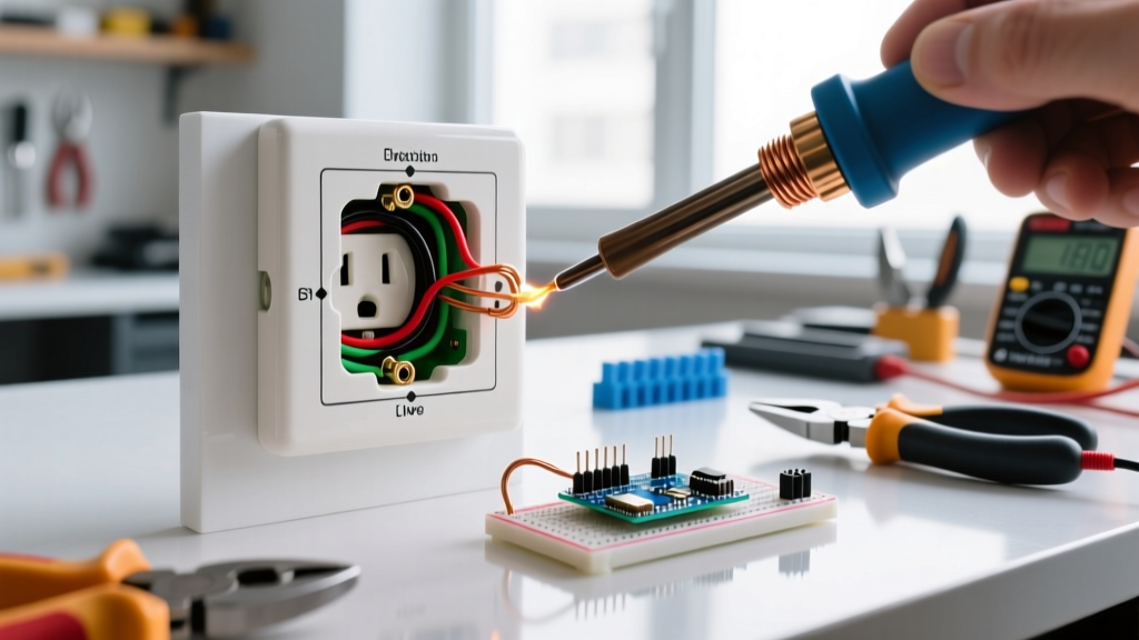
When you first pull off the cover plate of a residential receptacle, the physical mess of wires rarely matches the pristine wiring electrical outlet diagram printed on the back of the device or found in installation manuals. As an electrical inspector or advanced DIYer, your job is to bridge this gap. Relying solely on a cheap three-prong plug-in tester is a recipe for missed hazards, as these basic tools cannot detect bootleg grounds, multi-wire branch circuit (MWBC) miswiring, or high-resistance connections. According to the U.S. Consumer Product Safety Commission (CPSC), electrical receptacles are involved in thousands of residential fires annually, many stemming from degraded connections and improper wiring configurations that bypass standard visual inspections.
This guide moves beyond basic plug-in testers. We will dissect standard outlet diagrams, establish a rigorous field-testing protocol, and identify the "ghost faults" that deceive amateur inspectors. Whether you are verifying a new installation or auditing a 50-year-old home, understanding how to translate a schematic into a physical testing workflow is critical for safety and compliance.
The Anatomy of a Standard 120V Outlet Diagram
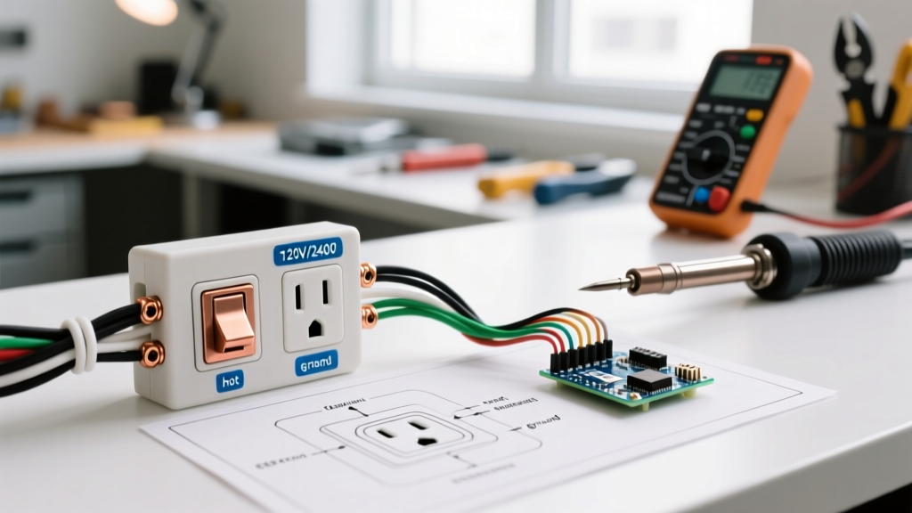
A standard NEMA 5-15R (15-amp) or 5-20R (20-amp) duplex receptacle diagram maps three critical termination points. While the colors are standardized, the physical execution in the field often deviates, leading to catastrophic failure modes under continuous load.
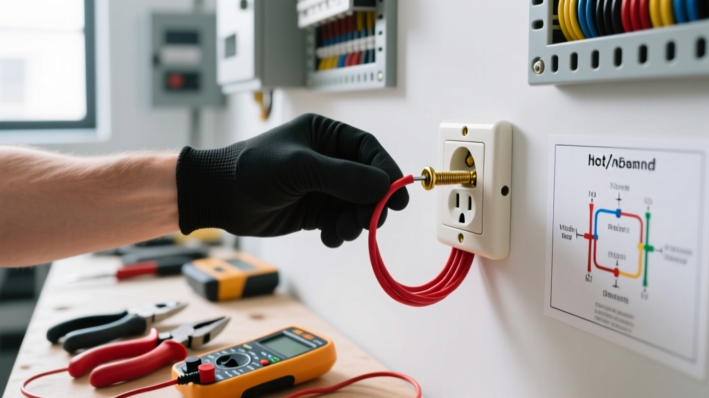
- Brass Terminals (Hot/Line): Connects to the black (or red) ungrounded conductor. This carries the 120V potential. Diagrams typically show the brass screw on the right side when the ground pin is facing down.
- Silver Terminals (Neutral/Grounded): Connects to the white or gray grounded conductor. This completes the circuit back to the panel. Reversing hot and neutral (reverse polarity) energizes the outer threaded shell of a screw-in lamp base, creating a severe shock hazard.
- Green Terminal (Equipment Ground): Connects to the bare copper or green insulated grounding conductor. This provides a low-impedance fault path to trip the breaker during a short circuit.
Inspector Note: Always verify the strip length against the manufacturer's diagram printed on the back of the yoke. For 14 AWG wire, the strip length is typically 3/4 inch. For 12 AWG, it is often 3/4 to 7/8 inch. Exposed copper outside the terminal housing creates an arc-flash and short-circuit risk.
2026 Inspection Toolkit: What You Actually Need
To properly verify a wiring electrical outlet diagram against physical reality, you need tools that measure voltage, continuity, and impedance without relying on the receptacle's internal spring tension. Here is a comparison of professional-grade testing equipment required for modern inspections.
| Tool Model | Avg. Price | Primary Function | Why It Beats Plug-In Testers |
|---|---|---|---|
| Klein Tools RT250 | $35 | GFCI & Polarity Testing | Features a magnetic hanger and clearly identifies open neutrals without relying on ambiguous LED light patterns. |
| Fluke T6-1000 | $230 | Open-Jaw Voltage & Current | Measures AC voltage and current simultaneously without metal-to-metal contact, ideal for checking energized pigtails. |
| Amprobe AT-3500 | $380 | Advanced Circuit Tracer | Traces specific breakers to receptacles and identifies MWBC shared neutrals hidden behind drywall. |
| Wiha Insulated Torque Screwdriver | $140 | Termination Verification | Ensures terminal screws meet NEC 110.14(D) torque specifications to prevent thermal runaway. |
The 4-Step Field Testing Protocol
Do not skip steps. A systematic approach ensures that hidden wiring errors—those not visible on a basic diagram—are exposed before the system is energized for continuous use.
Step 1: Visual and Mechanical Verification (De-energized)
With the breaker locked out, remove the receptacle from the box. Inspect the termination method. "Backstabbed" push-in connections (using the quick-wire holes on the back) are notorious for failing under 12A continuous loads due to weakened internal spring clips. Action: Migrate all backstabbed wires to the side-binding terminal screws or use proper pigtailing with Wago 221 lever nuts.
Step 2: The Bootleg Ground Continuity Test
A "bootleg ground" occurs when a previous worker jumps a wire from the neutral silver screw to the green ground screw to trick a basic plug-in tester into showing a "Correct" reading. Action: Using a multimeter set to continuity (ohms), place one probe on the neutral bus bar in the panel and the other on the ground pin of the receptacle. If you read near-zero resistance, but there is no continuous bare/green wire running back to the panel's ground bus, you have identified a dangerous bootleg ground.
Step 3: Energized Voltage and Polarity Check
Energize the circuit. Using a digital multimeter (DMM) or solenoid voltage tester, measure between Hot and Neutral (should be 120V ±5%), Hot and Ground (120V ±5%), and Neutral to Ground (should be <2V). A Neutral-to-Ground reading above 2V indicates a high-resistance neutral connection or an overloaded shared neutral upstream.
Step 4: GFCI and AFCI Functional Testing
If the diagram indicates a downstream protected configuration (common in kitchens and bathrooms), test the upstream GFCI device. Use the "Test" button on the GFCI itself, not just the black button on a plug-in tester, as the plug-in tester relies on the presence of an equipment ground to trip the internal circuit, which may not exist in older retrofits.
Safety Warning: Never assume a receptacle is de-energized just because a non-contact voltage tester (NCVT) reads zero. NCVTs can yield false negatives due to shielded cables or dead-front voltage. Always verify with a DMM on a known live source, test the target, and re-test the known live source (Live-Dead-Live protocol).
Ghost Faults: When the Diagram Doesn't Match the Box
Advanced troubleshooting requires understanding complex circuit topologies that standard diagrams omit. The most dangerous of these is the Multi-Wire Branch Circuit (MWBC).
An MWBC uses two hot wires (typically black and red, on opposite phases) sharing a single white neutral wire. If an electrician breaks the neutral tab on the receptacle to feed downstream devices but fails to pigtail the neutral, the downstream receptacles become series-connected. If the shared neutral is ever disconnected at the panel or an upstream junction, the downstream 120V appliances will suddenly be subjected to 240V, instantly destroying electronics and creating a fire hazard.
Inspection Fix: The National Fire Protection Association (NFPA) mandates that all MWBCs must have a simultaneous disconnect mechanism (a handle tie or a double-pole breaker). During your inspection, if you see a red and black wire on the same yoke, trace them back to the panel to verify the handle tie is present and the neutral is properly pigtailed inside the junction box, never relying on the receptacle's internal metal tab to carry the neutral current.
NEC Torque Requirements: The Missing Link in Outlet Diagrams
One critical piece of information missing from almost every consumer-facing wiring electrical outlet diagram is the required termination torque. Since the adoption of NEC 110.14(D), electrical inspectors are required to verify that terminations are tightened to the manufacturer's specified torque using a calibrated tool.
For standard Leviton and Eaton 15A and 20A spec-grade receptacles, the required torque is typically 14 inch-pounds. Under-torquing leads to micro-arcing and thermal expansion/contraction cycles that eventually loosen the screw, causing a high-resistance fault and melting the receptacle face. Over-torquing can strip the brass threads or snap the screw head off entirely. Always keep a calibrated inch-pound torque screwdriver in your inspection kit to verify these connections during rough-in and final inspections.
Final Thoughts on Receptacle Verification
A wiring electrical outlet diagram is merely a suggestion of how the device should be wired. The reality of the junction box is governed by the skill of the installer and the degradation of time. By utilizing professional-grade testing equipment, adhering to the Live-Dead-Live protocol, and actively hunting for bootleg grounds and MWBC violations, you elevate your inspection from a superficial glance to a comprehensive safety audit. Always prioritize mechanical integrity and code compliance over simple continuity readings.