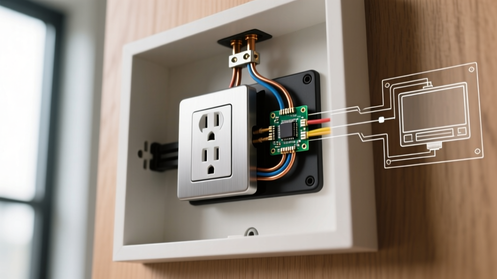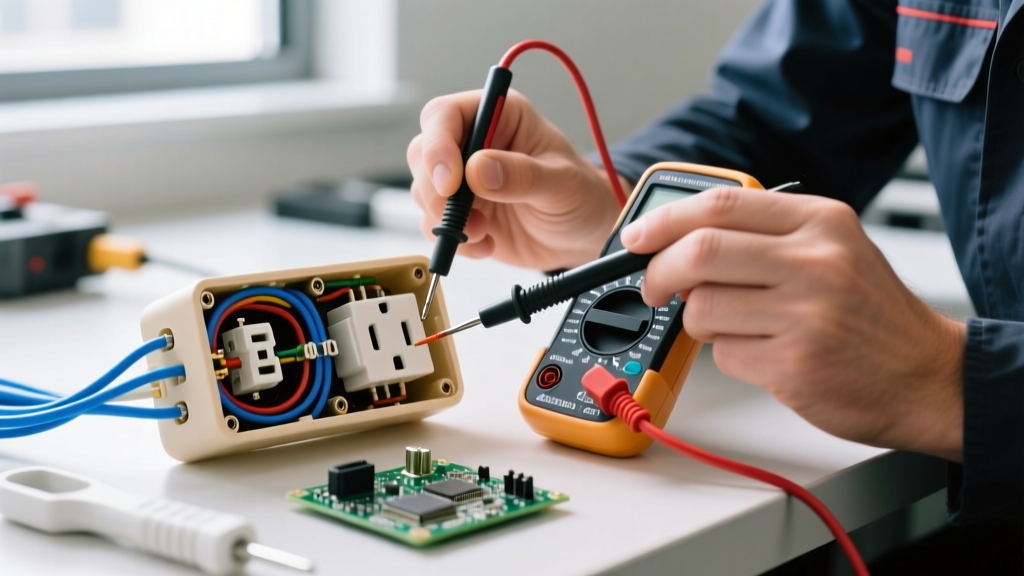

Why Upgrade Your Electrical Outlets?
Electrical receptacles are the most heavily used components in any residential wiring system. Over time, the internal brass contacts fatigue, leading to loose plug retention, arcing, and potential fire hazards. If you are searching for how to wire an electrical outlet, you are likely dealing with a worn-out receptacle, a damaged faceplate, or an outdated 2-prong setup that lacks modern safety features.
Upgrading your outlets is not just about restoring power; it is about bringing your home up to modern safety standards. The National Fire Protection Association (NFPA) mandates Tamper-Resistant (TR) receptacles in all new residential constructions and major renovations. Furthermore, replacing standard builder-grade outlets with commercial-specification models drastically improves termination reliability and lifespan.
NEC Safety Mandate: According to the National Electrical Code (NEC), all 15-amp and 20-amp, 125-volt and 250-volt non-locking receptacles installed in dwelling units must be tamper-resistant (TR) to prevent childhood electrical shock injuries.
Materials and Tool Stack for Modern Replacements
Professional electricians do not use the cheapest builder-grade receptacles found in bulk bins. For a reliable upgrade, invest in specification-grade (spec-grade) TR receptacles. Below is the recommended tool and material stack for a standard 15-amp upgrade.
| Item | Recommended Model / Brand | Estimated Cost | Purpose |
|---|---|---|---|
| 15A TR Receptacle | Leviton T5262-E (Spec Grade) | $2.80 - $3.50 | Primary outlet replacement with side/back wiring clamps. |
| Wire Strippers | Klein Tools 11055 | $24.00 | Precision stripping for 14 AWG and 12 AWG solid copper. |
| Wire Connectors | Wago 221-413 Lever Nuts | $0.60 each | Secure, tool-free pigtailing and splicing. |
| Voltage Tester | Klein NCVT-3 (Dual Range) | $35.00 | Verifying absence of voltage before touching wires. |
| Receptacle Tester | Gardner Bender GRT-501 | $12.00 | Post-installation verification of wiring polarity. |
Wiring Methods: Back-Wire vs. Side-Wire vs. Push-In
Understanding termination methods is the most critical part of learning how to wire an electrical outlet correctly. The method you choose dictates the longevity and safety of the connection.
1. Side-Wiring (The Loop Method)
This is the traditional method where you form a J-hook in the stripped wire and loop it clockwise around the terminal screw. As the screw is tightened, it pulls the loop tighter. Pro Tip: Strip exactly 3/4 inch of insulation. If the loop is too large, bare wire will be exposed past the screw head, creating a short-circuit hazard when the outlet is pushed back into the junction box.
2. Back-Wiring (The Clamp Method)
Spec-grade receptacles like the Leviton T5262-E feature internal screw-clamp plates. You insert a straight, stripped wire (usually 5/8 inch) into the back hole and tighten the side screw. The internal brass plate clamps down on the wire. This is the preferred method for professionals because it provides a massive surface area contact, prevents strand splaying, and eliminates the risk of exposed bare wire.
3. Push-In Backstab (The Failure Mode)
Cheap, builder-grade outlets feature spring-loaded push-in holes on the back. Never use these. The Consumer Product Safety Commission (CPSC) and independent electrical forensic engineers frequently cite backstab connections in residential fire investigations. The small internal spring teeth bite into the wire, but thermal expansion and contraction over time cause the spring to relax, leading to high-resistance connections, severe arcing, and melted plastic housings.
Step-by-Step: How to Wire an Electrical Outlet
Follow this exact sequence to ensure a safe, code-compliant installation.
- Kill the Power and Verify: Turn off the branch circuit breaker. Use your Klein NCVT-3 dual-range tester to verify the absence of voltage at the hot slot (the shorter slot) and the neutral slot. Test a known live outlet first to ensure your tester's battery is functional.
- Extract and Inspect: Remove the faceplate and unscrew the old receptacle. Pull it out gently. Inspect the wire insulation. If the insulation is cracked, brittle, or crumbling (common in pre-1950s knob-and-tube or early cloth-wired homes), stop and consult a licensed electrician to rewire the branch.
- Prepare the Wires: Cut off the old, damaged tips of the copper wires. Use your Klein 11055 strippers to remove exactly 3/4 inch of insulation for side-wiring, or 5/8 inch for back-wiring. Ensure no nicks or gouges are left on the copper conductor.
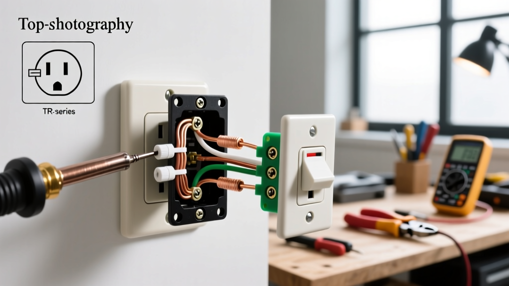
- Make the Terminations: If side-wiring: Form a clockwise hook and seat it under the brass (hot) and silver (neutral) screws. If back-wiring: Insert the straight wire fully into the clamp hole until the insulation touches the receptacle body, then torque the screw down firmly.
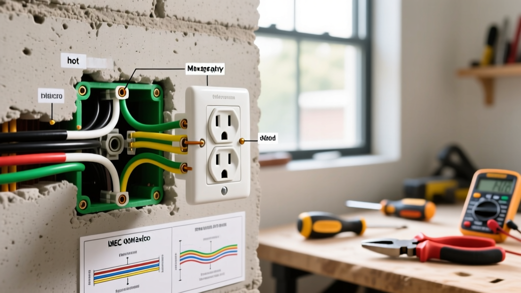
- Ground Connection: Connect the bare copper or green insulated ground wire to the green grounding screw at the bottom of the yoke. If the metal junction box is grounded, you must also run a pigtail from the box to the receptacle's ground screw.
- Secure and Test: Carefully fold the wires in an accordion pattern into the box. Mount the receptacle using the provided 6-32 machine screws. Attach the faceplate, restore power at the breaker, and verify correct wiring using your Gardner Bender receptacle tester (two yellow lights indicate correct wiring).
Upgrade Scenarios: Edge Cases and Special Wiring
Not every replacement is a simple swap. You must identify your specific wiring scenario to choose the correct hardware.
| Scenario | Identifying Features | Required Hardware / Action |
|---|---|---|
| Standard 15A Copper | Black/White/Bare wires; 14 AWG or 12 AWG copper. | Standard 15A TR Receptacle (e.g., Leviton T5262-E). |
| 20A Kitchen/Bath Circuit | 12 AWG copper wire; 20A breaker in the panel. | 20A TR Receptacle (e.g., Leviton T5362-E) with the T-shaped neutral slot. |
| Aluminum Branch Wiring | Silver-colored wire (late 1960s/early 1970s homes). | CRITICAL: Must use CO/ALR rated receptacles (e.g., Leviton 1729-TC). Standard brass screws will cause galvanic corrosion and fire. |
| 2-Prong to 3-Prong (No Ground) | Older homes with no equipment ground wire in the box. | Install a GFCI receptacle and label it "GFCI Protected, No Equipment Ground" per NEC 406.4(D)(2). Do NOT bootleg a ground to the neutral. |
Addressing the Aluminum Wire Hazard
One of the most dangerous edge cases when learning how to wire an electrical outlet in older homes is encountering aluminum branch wiring. Between 1965 and 1973, aluminum was widely used due to copper shortages. Aluminum oxidizes rapidly when exposed to air and expands/contracts at a different rate than copper. If you terminate aluminum wire to a standard brass screw terminal, the connection will loosen over time, oxidize, and create extreme heat.
If you discover aluminum wiring, you must use receptacles specifically stamped with CO/ALR (Copper-Aluminum Revised). These feature specialized nickel-plated or iron-alloy terminal screws designed to grip aluminum without causing galvanic corrosion. Alternatively, you can pigtail the aluminum wire to a short copper lead using COPALUM crimps or specialized purple wire nuts (Ideal Industries No. 65), but the CO/ALR receptacle is the safest direct-termination method.
Final Verification and Torque Checks
The difference between a DIY hack-job and a professional installation comes down to torque and dress. While residential receptacles do not strictly require a calibrated torque screwdriver like panel breakers do, the terminal screws must be driven tight—typically around 14 inch-pounds. A loose screw increases electrical resistance, which generates heat proportional to the square of the current (I²R losses).
Before pushing the receptacle into the box, ensure no bare ground wires are touching the hot brass terminals. Dress the wires neatly, folding the ground wire to the back of the metal or fiberglass box, followed by the neutral, and finally the hot wire. This prevents the faceplate screws from piercing the hot wire insulation when tightened. By following this comprehensive upgrade guide, you ensure your electrical system remains safe, code-compliant, and reliable for decades to come.