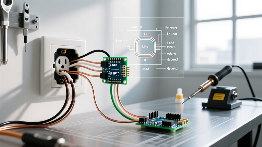

Mastering Receptacle Replacement: A Wiring Diagram Approach
Learning how to change an electrical outlet goes far beyond simply swapping one plastic faceplate for another. As electrical systems age, or as modern code requirements evolve, replacing a standard duplex receptacle requires a firm understanding of circuit topology. Whether you are dealing with an end-of-run termination, a middle-of-run daisy chain, or a split-wired switched configuration, referencing the correct wiring diagram is critical for safety and code compliance.
This guide serves as a comprehensive wiring diagram reference for standard 15-amp and 20-amp, 120-volt receptacles. We will bypass generic advice and focus on exact terminal mappings, National Electrical Code (NEC) 2026 requirements, and professional-grade termination techniques.
Safety Protocols and Essential Tooling
Before consulting any wiring diagram, you must secure the workspace. The Occupational Safety and Health Administration (OSHA) mandates strict lockout/tagout procedures for electrical work. Never rely solely on a wall switch to de-energize a circuit.
- Voltage Verification: Use a non-contact voltage tester (e.g., Klein Tools NCVT-3) at the breaker panel and at the receptacle face to confirm zero voltage.
- Wire Stripping: Use a precision stripper (e.g., Klein 11055) set to the exact gauge. 14 AWG for 15A circuits; 12 AWG for 20A circuits.
- Torque Application: Per NEC 110.14(D), terminals for 14 AWG through 10 AWG wires must be tightened to the manufacturer's specified torque. For standard receptacles like the Leviton 5262-SW, this is typically 14 in-lbs. Use a calibrated torque screwdriver (e.g., Wiha 2850).
Anatomy of a Standard Duplex Receptacle
To interpret the wiring diagrams below, you must understand the physical terminal layout of a standard NEMA 5-15R or 5-20R receptacle.
| Terminal Color | Screw Material | Function | Wire Color (Standard) | Connection Rule |
|---|---|---|---|---|
| Brass | Brass | Hot (Line/Load) | Black, Red, Blue | Connects to the circuit breaker. Carries 120V. |
| Silver | Steel/Nickel | Neutral | White, Gray | Returns current to the panel. Must be continuous. |
| Green | Brass/Steel | Equipment Ground | Bare Copper, Green | Safety path for fault currents. Never carry load. |
Wiring Diagram 1: End-of-Run (Single Feed)
The end-of-run configuration is the simplest topology. The circuit originates at the breaker panel and terminates at this specific receptacle. There are no downstream devices to feed.
Topology Matrix
| Incoming Cable (Romex/NM-B) | Receptacle Terminal | Action |
|---|---|---|
| 1x Black (Hot) | Brass Screw (Top or Bottom) | Form a J-hook, loop clockwise under screw. |
| 1x White (Neutral) | Silver Screw (Top or Bottom) | Form a J-hook, loop clockwise under screw. |
| 1x Bare (Ground) | Green Ground Screw | Loop clockwise. Ensure no bare wire extends past the yoke. |
Pro-Tip: Even though modern receptacles feature 'push-in' backstab terminals, professional electricians universally avoid them for solid wire. Backstab connections rely on a small internal spring clip that can loosen over time due to thermal expansion and contraction, leading to high-resistance arcing. Always use the side-wire screw terminals.
Wiring Diagram 2: Middle-of-Run (Daisy Chain)
When the receptacle is located in the middle of a circuit, it must receive power from the panel (Line) and pass power to the next device (Load). This requires handling two sets of cables.
The Pigtailing Mandate
While you can connect two black wires to one brass screw and two white wires to one silver screw (using the side wire clamps), the National Fire Protection Association (NFPA 70 / NEC) and best practices strongly dictate pigtailing the neutral. If a daisy-chained neutral is broken by removing the receptacle, downstream devices can experience severe voltage fluctuations, potentially destroying connected electronics.
Middle-of-Run Pigtailing Diagram
| Wire Type | Cable 1 (Line) | Cable 2 (Load) | Pigtail Wire | Receptacle Terminal |
|---|---|---|---|---|
| Hot | Black | Black | 6-inch Black 14/12 AWG | Brass Screw |
| Neutral | White | White | 6-inch White 14/12 AWG | Silver Screw |
| Ground | Bare | Bare | 6-inch Bare/Green 14/12 AWG | Green Screw |
Execution: Use a wire nut (e.g., Ideal 341 Yellow or 339 Red, depending on gauge) to join the Line wire, Load wire, and Pigtail wire together. Ensure at least 3/4 inch of insulation is stripped and the wire nut is twisted until the wires twist together outside the nut.
Wiring Diagram 3: Split-Wired (Switched Half-Hot)
In living rooms and bedrooms, it is common to have a receptacle where the top half is controlled by a wall switch, and the bottom half is always hot. This requires a 3-wire cable (Black, Red, White, Bare) and modifying the receptacle itself.
Preparation: Breaking the Fin
On the brass (hot) side of the receptacle, there is a small metal connecting tab (fin) between the top and bottom screws. Using needle-nose pliers, bend this tab back and forth until it snaps off. Do not break the silver side fin.
Split-Wired Topology
- Top Brass Screw: Connect the Red wire (Switched Hot from the wall switch).
- Bottom Brass Screw: Connect the Black wire (Constant Hot from the panel).
- Silver Screw: Connect the White wire (Shared Neutral).
- Green Screw: Connect the Bare wire (Ground).
Step-by-Step Replacement Execution
- De-energize and Verify: Turn off the breaker. Test the receptacle slots and the bare ground wire with an NCVT-3.
- Extract and Inspect: Remove the cover plate and mounting screws. Pull the receptacle out. Inspect the drywall box for heat damage or melted plastic. If the box is compromised, it must be replaced with an old-work bracket.
- Assess the Wiring: Check for 'backstabbed' wires. If present, cut them off, strip them fresh to 5/8 inch, and prepare for side-wiring.
- Terminate: Form precise J-hooks with your pliers. Hook them clockwise around the terminal screws so that tightening the screw pulls the loop tighter.
- Torque: Tighten to 14 in-lbs. Ensure no bare copper is exposed outside the terminal yoke.
- Fold and Mount: Carefully fold the wires in an accordion pattern into the back of the box. Mount the receptacle, ensuring it is plumb. Use shims if the box is recessed more than 1/4 inch into the wall (NEC 314.20).
- Test: Restore power. Use a receptacle tester (e.g., Gardner Bender GFI-3501) to verify correct wiring and test the GFCI/AFCI trip mechanism if applicable.
Troubleshooting Edge Cases and Code Violations
When opening older homes, you will inevitably encounter wiring anomalies. Here is how to identify and correct them.
| Anomaly | Description & Risk | Correction Protocol |
|---|---|---|
| Bootleg Ground | A jumper wire connects the neutral (silver) terminal to the ground (green) terminal to trick a tester into showing a 'correct' reading. Highly dangerous; energizes the ground path if the neutral fails. | Remove the jumper immediately. If no true ground exists in the box, install a GFCI receptacle and label it 'No Equipment Ground' per NEC 406.4(D). |
| Reverse Polarity | Hot (Black) is on the Silver screw; Neutral (White) is on the Brass screw. The device works, but the internal switch of the appliance won't break the hot leg. | Swap the black and white wires to their respective Brass and Silver terminals. |
| Overstripped Wires | More than 5/8 inch of insulation removed, leaving bare copper exposed along the terminal yoke. Creates a severe shock and short-circuit hazard. | Cut the wire back, re-strip to exactly 5/8 inch using the gauge hole on your wire strippers, and re-terminate. |
| Mismatched Amperage | A 15A receptacle (NEMA 5-15R) installed on a 20A breaker circuit with 12 AWG wire. | While NEC allows 15A receptacles on 20A circuits if there are multiple receptacles, if this is a single-receptacle circuit, it must be upgraded to a 20A receptacle (NEMA 5-20R, e.g., Hubbell 5362). |
Final Considerations for 2026 Installations
As of the latest NEC updates, Tamper-Resistant (TR) receptacles are mandated in virtually all residential living spaces, including guest rooms and dormitories. Furthermore, Arc-Fault Circuit Interrupter (AFCI) and Ground-Fault Circuit Interrupter (GFCI) requirements have expanded. When changing an outlet in a kitchen, bathroom, garage, or outdoor location, you must replace it with a GFCI receptacle unless the circuit breaker itself provides GFCI protection. Always verify local jurisdiction amendments, as local inspectors may enforce stricter interpretations of the national code.