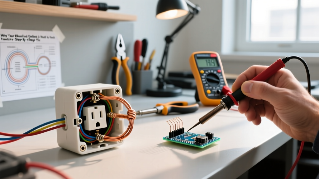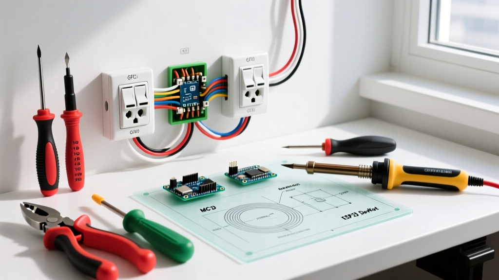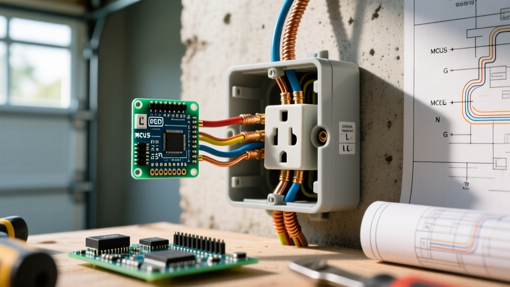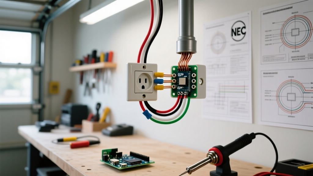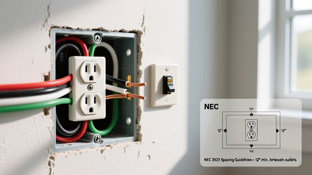

Understanding the Electrical Outlet Baseboard Concept
Integrating an electrical outlet baseboard system is a premium architectural solution designed to maintain clean sightlines, accommodate low-profile furniture, and eliminate the visual clutter of standard wall-height receptacles. Unlike standard outlets mounted 12 to 18 inches above the finished floor, baseboard outlets are installed directly into or immediately above the baseboard trim, typically sitting 2 to 4 inches off the floor. While aesthetically superior, this installation method introduces unique electrical and carpentry challenges. Shallow wall cavities, interference with floor joists, and the high risk of nail or screw penetration during trim installation demand strict adherence to specialized wiring diagrams and National Electrical Code (NEC) protocols.
NEC Code Compliance & Spacing Rules
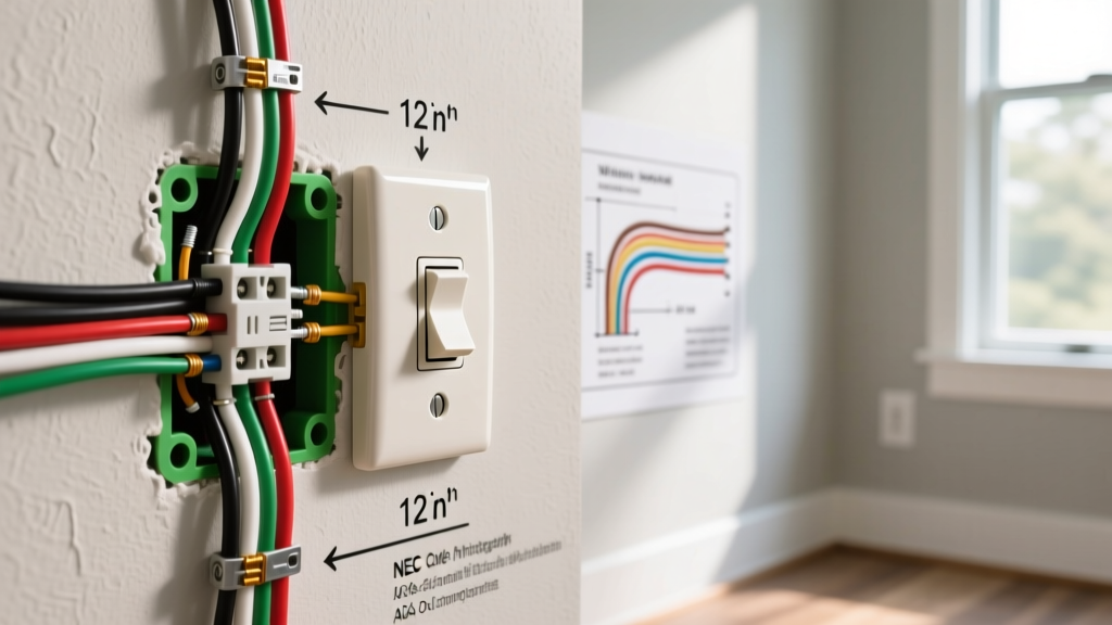
When planning your electrical outlet baseboard layout, you must adhere to the same spatial requirements as standard receptacles, but with heightened physical protection mandates. According to the National Fire Protection Association (NFPA), NEC Article 210.52(A)(1) dictates that no point along the floor line in any wall space can be more than 6 feet from a receptacle. This effectively maintains the standard 12-foot spacing rule between outlets, even when they are dropped to the baseboard level.
Physical Protection and Nail Plates
The most critical code consideration for baseboard wiring is NEC Article 300.4(D). Because baseboard trim is frequently installed using long pneumatic finish nails or screws, cables routed horizontally through studs just above the floor plate are in the direct line of fire. If the cable is less than 1.25 inches from the edge of the stud, a steel nail plate (minimum 1/16 inch thick) must be installed over the stud face to protect the NM-B (Romex) cable. Failing to install nail plates is the leading cause of arc faults and subsequent fires in baseboard outlet installations.
Component Selection: Shallow Boxes & Receptacles
Standard 20-cubic-inch electrical boxes (typically 2.5 to 3.5 inches deep) will protrude through the drywall or interfere with the baseboard trim profile. For a flush electrical outlet baseboard installation, you must specify shallow boxes and compact receptacles.
- Electrical Box: Raco 187 1-Gang Shallow Switch Box. Depth: 1.25 inches. Capacity: 12.5 cubic inches. Average cost: $1.85. The shallow depth allows it to sit flush against the drywall without hitting the vapor barrier or exterior insulation.
- Receptacle: Leviton 5262-SW Shallow Duplex Receptacle. Average cost: $3.40. This model is specifically engineered with a reduced rear yoke profile to fit into 1.25-inch shallow boxes without crushing the 12 AWG or 14 AWG conductors.
- Cover Plate: Leviton 800 Series 1-Gang Flush Plate. Cost: $1.20. Ensure the plate dimensions do not exceed the routed cavity in your MDF or wood baseboard trim.
Comparison Matrix: Standard vs. Shallow Baseboard Boxes
Selecting the correct enclosure is vital for heat dissipation and wire bending radius. The National Electrical Manufacturers Association (NEMA) provides guidelines on enclosure sizing, but field conditions dictate your final choice.
| Feature | Standard 1-Gang Box (e.g., Carlon B618R) | Shallow Baseboard Box (e.g., Raco 187) |
|---|---|---|
| Depth | 3.0 inches | 1.25 inches |
| Volume | 20.0 cubic inches | 12.5 cubic inches |
| Max 12 AWG Wires Allowed | 9 conductors | 5 conductors |
| Baseboard Trim Interference | High (requires deep routing) | None (sits flush to drywall) |
| Ideal Use Case | Standard 16-inch wall height | Electrical outlet baseboard integration |
Step-by-Step Wiring Diagram & Procedure
Executing the wiring diagram for a baseboard outlet requires precision, particularly regarding wire bending radius. NEC 300.34 requires that the bending radius of the conductors inside the box must not be less than specified values to prevent insulation damage and heat buildup.
Step 1: Cable Routing and Protection
- Drill a 3/4-inch hole through the wall studs exactly 2.5 inches above the finished floor level. This places the cable safely below the standard baseboard trim height but above the bottom sole plate.
- Run 12/2 NM-B cable (for 20A circuits) or 14/2 NM-B (for 15A circuits) through the studs.
- Apply 1/16-inch steel nail plates to every stud face where the cable passes within 1.25 inches of the edge. Secure plates with 1/2-inch pan-head screws.
Step 2: Mounting the Shallow Box
Cut the drywall using a rotary tool or oscillating multi-tool. Insert the Raco 187 shallow box. Because baseboard outlets endure higher mechanical stress from vacuum cleaners and foot traffic, do not rely solely on drywall clips. Use the integrated side nails to secure the box directly to the stud, or use Madison-style metal hangers (old work brackets) tightened firmly against the drywall backside.
Step 3: Termination in Confined Spaces
Strip the NM-B sheathing so that exactly 1/4 inch of sheath enters the box. Strip 3/4 inch of insulation from the conductors. Because the Raco 187 box is only 1.25 inches deep, you cannot use standard loop-wrapping techniques if space is too tight. Instead, use a pigtail method:
- Connect the incoming and outgoing black wires to a 6-inch 12 AWG black pigtail using a Wago 221 lever nut (which requires less depth than a standard wire nut).
- Connect the pigtail to the brass screw on the Leviton 5262-SW receptacle.
- Repeat for the white neutral wires and the bare copper ground wires, ensuring the ground pigtail is attached to the green grounding screw and the metal box (if using a steel box like the Raco 187).
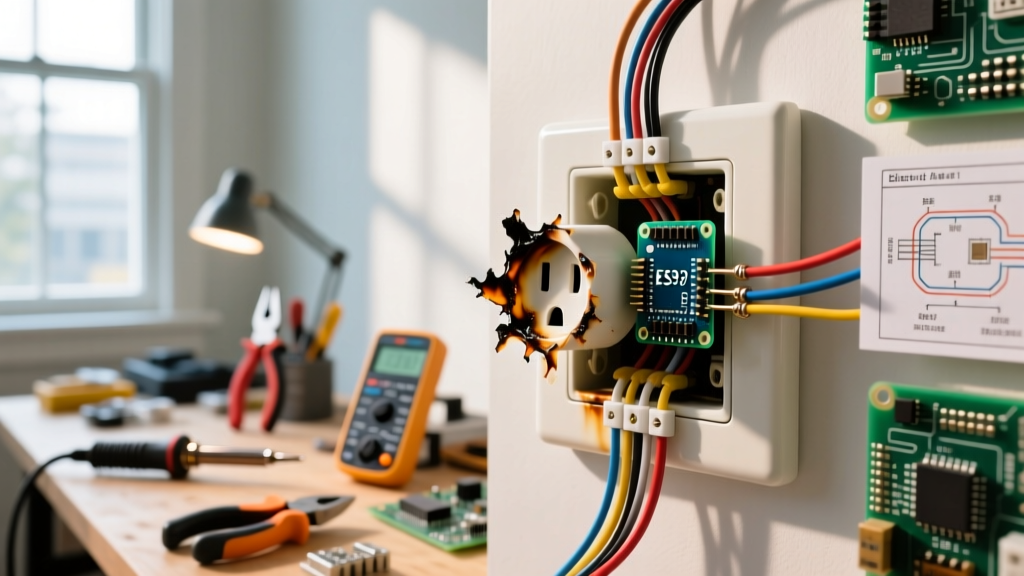
Critical Warning: Never fold or crush 12 AWG wires forcefully into a 12.5 cubic inch shallow box. If the box fill calculation exceeds the limit, or if the wires are kinked to force the receptacle in, the mechanical stress will degrade the insulation over time, leading to a short circuit. Always use Wago lever connectors to minimize bulk.
Edge Cases: GFCI Requirements & Exterior Walls
When your electrical outlet baseboard layout intersects with exterior walls, you face two distinct challenges: insulation compression and GFCI mandates. As jurisdictions adopt the 2023 and upcoming 2026 NEC cycles, Ground Fault Circuit Interrupter (GFCI) protection is required in broader residential zones. Standard GFCI receptacles are notoriously deep (often exceeding 1.75 inches) and will not fit into a 1.25-inch shallow baseboard box.
The Solution: Do not attempt to jam a standard GFCI into a shallow box. Instead, use a standard duplex receptacle at the baseboard location and protect it via a GFCI circuit breaker in the main panel, or install a Hubbell Wiring Systems feed-through GFCI at the first standard-depth box upstream from the baseboard outlet. Furthermore, on exterior walls, ensure the shallow box does not compress the rigid foam insulation, which can create a thermal bridge and lead to condensation inside the electrical box during winter months.
Troubleshooting Common Baseboard Outlet Failures
Issue: Baseboard Trim Will Not Sit Flush Against the Wall
Cause: The drywall mud around the shallow box is too thick, or the box flanges are not fully recessed. Fix: Use a rasp to shave the back of the MDF or wood baseboard trim. Do not route out the front face of the trim. Create a 1/8-inch relief channel on the backside of the baseboard directly over the box flanges to allow the trim to sit perfectly plumb against the drywall.
Issue: Receptacle Face Sits Below the Baseboard Surface
Cause: The baseboard trim is thicker than the receptacle yoke protrusion. Fix: Install a 1/4-inch or 1/2-inch plastic receptacle extender ring (e.g., Arlington Industries BE1) between the shallow box and the receptacle. This brings the face of the outlet flush with the routed opening in the baseboard trim, eliminating a dangerous gap where dust and debris can enter the box.
Frequently Asked Questions (FAQ)
Can I run the wiring horizontally through the floor joists instead of the wall studs?
Yes, but this requires drilling up through the bottom sole plate. If you are on a concrete slab, this is impossible without core drilling. For second-story installations, you can run the cable through the floor cavity, but you must use fire-stop caulk around the penetration point where the cable enters the wall cavity to maintain the fire rating of the floor assembly.
Are floor outlets a better alternative to baseboard outlets?
Floor outlets (installed directly in the hardwood or tile) require specialized UL-listed floor boxes (like the Hubbell FBA series) that cost upwards of $45 each and require precise subfloor cutting. Baseboard outlets are significantly cheaper, easier to wire using standard NM-B cable, and do not pose a tripping hazard or water-ingress risk during floor mopping.
What is the maximum number of wires allowed in a Raco 187 shallow box?
According to NEC box fill calculations, a 12.5 cubic inch box can hold a maximum of five 12 AWG conductors (excluding grounds and clamps). This typically allows for one incoming 12/2 cable and one outgoing 12/2 cable, plus the receptacle itself. You cannot use a shallow box as a multi-cable junction point.