
The Critical Importance of Code-Compliant Plug Wiring
Improperly wired attachment plugs are a leading cause of industrial electrical fires and equipment failure. When addressing plug electrical wiring, electricians and DIYers must navigate a complex matrix of National Electrical Code (NEC) requirements, UL standards, and OSHA workplace safety regulations. A poorly terminated plug doesn't just trip breakers; it creates high-resistance connections that generate intense heat, leading to insulation meltdown and arc faults.
In the 2026 electrical landscape, the emphasis on terminal torque, strain relief, and exact wire preparation has never been higher. This comprehensive safety guide breaks down the exact specifications, failure modes, and step-by-step procedures required to execute flawless plug electrical wiring on standard NEMA 5-15P and 5-20P configurations.
Anatomy of a Code-Compliant Attachment Plug
Before stripping a single wire, you must select the correct plug body for your application. Using a residential-grade plug on a continuous industrial load is a direct violation of safety best practices and often voids equipment warranties.
- Residential/Commercial Grade (e.g., Leviton 5266-C): Rated for 15A, 125V. Features standard brass and silver terminal screws. Suitable for intermittent loads like lamps, vacuums, and light power tools.
- Industrial/Spec Grade (e.g., Hubbell 5266A or Pass & Seymour 5266X): Rated for 15A, 125V, but built with high-impact nylon, internal steel cord grips, and back-wiring clamps. Designed for continuous heavy-duty use and harsh environments.
According to the National Electrical Manufacturers Association (NEMA), wiring devices must strictly adhere to dimensional and performance standards to ensure interchangeability and safety across different manufacturers.
NEC & OSHA Code Requirements for Flexible Cords
Plug electrical wiring is governed primarily by NEC Article 400 (Flexible Cords and Cables) and Article 406 (Receptacles, Cord Connectors, and Attachment Plugs). Furthermore, OSHA enforces these standards in commercial environments under 29 CFR 1910.305.
OSHA Regulation 1910.305(g)(1)(iii): Flexible cords shall be connected to devices and to fittings so that tension will not be transmitted to joints or terminal screws. Strain relief is not optional; it is a federal safety mandate.
The Strain Relief Mandate
The most common code violation in plug wiring is failing to secure the outer jacket of the cord. The internal strain relief clamp (or cord grip) must bite down exclusively on the outer insulating jacket of the cord (e.g., SJTOW or SOOW), never on the individual inner conductors. If tension pulls the inner wires, the terminal screws will eventually loosen, creating an arc flash hazard.
Wire Gauge and Amperage Matrix
Matching the cord gauge to the plug rating and the load is critical. Overloading a 15A plug with a 20A continuous draw will cause thermal degradation of the brass terminals.
| Cord Type | Wire Gauge (AWG) | Max Amperage | Compatible Plug NEMA | Typical Application |
|---|---|---|---|---|
| SJTOW | 16 AWG | 10A | NEMA 5-15P | Light duty electronics, lamps |
| SJTOW / SJOW | 14 AWG | 15A | NEMA 5-15P | Standard power tools, vacuums |
| SOOW | 12 AWG | 20A | NEMA 5-20P | Heavy machinery, continuous 20A loads |
| SOOW | 10 AWG | 30A | NEMA L5-30P (Twist-Lock) | Generators, RV shore power |
Step-by-Step Plug Electrical Wiring Procedure
Follow this exact sequence to ensure a low-resistance, code-compliant termination. This procedure assumes you are wiring a standard NEMA 5-15P plug with a 14/3 SJTOW cord.
Step 1: Precision Jacket Stripping and Conductor Prep
Use a dedicated cord-stripping tool (like the Klein Tools 1412) to score the outer jacket. Remove exactly 2.5 inches of the outer jacket. Next, strip exactly 3/4 inch (19mm) of insulation from the black (hot), white (neutral), and green/bare (ground) conductors.
Critical Edge Case: If you strip less than 3/4 inch, the wire insulation will get trapped under the terminal screw head. This 'insulation trap' prevents copper-to-brass contact, causing massive resistance and localized heating. If you strip more than 3/4 inch, exposed copper will protrude past the terminal, creating a shock and short-circuit hazard.
Step 2: Forming the Hook and Terminal Selection
Using needle-nose pliers, form a tight, clockwise hook (shepherd's hook) at the end of each stripped conductor. The clockwise direction ensures that tightening the terminal screw pulls the hook closed rather than pushing it out.
- Black Wire (Hot): Connects to the Brass terminal (the narrower slot on the plug face).
- White Wire (Neutral): Connects to the Silver terminal (the wider slot on the plug face).
- Green/Bare Wire (Ground): Connects to the Green terminal (the U-shaped pin).
Mnemonic: "Black to Brass saves your..." (ensures correct polarity to prevent shock hazards from improperly wired appliance chassis).
Step 3: Torque and Termination
Seat the wire hook fully under the terminal screw head and the integrated washer. Tighten the screw. While the NEC heavily emphasizes calibrated torque screwdrivers for breaker terminations (NEC 110.14(D)), best practices for industrial-grade plugs (like the Hubbell 5266A) recommend tightening terminal screws to approximately 14 to 16 inch-pounds. This prevents 'cold flow' relaxation, where copper deforms under pressure over time, leading to a loose connection.
Step 4: Engaging the Strain Relief
Route the cord through the plug body. Ensure the outer jacket extends past the internal strain relief bar by at least 1/4 inch. Tighten the strain relief screws until the jacket is firmly gripped. Perform the 'pull test': give the cord a firm 20-pound yank. The inner conductors should not move at the terminal screws.
Advanced Troubleshooting and Failure Mode Analysis
Even with meticulous plug electrical wiring, environmental factors and mechanical stress can degrade connections. Modern electrical maintenance relies on predictive diagnostics rather than waiting for catastrophic failure.
Thermal Imaging for High-Resistance Faults
Using a thermal imaging camera (such as the FLIR E8-XT), scan the plug face while the equipment is under a continuous load for at least 15 minutes. A healthy plug will show a uniform temperature profile. A temperature delta (ΔT) of 15°F to 40°F between the hot and neutral blades indicates a loose terminal screw, stranded wire fraying, or an insulation trap. Any ΔT exceeding 40°F requires immediate plug replacement.
Continuity and Polarity Verification
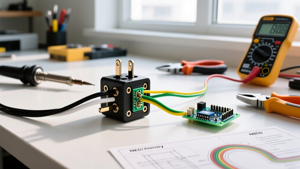
Before plugging the newly wired cord into a live receptacle, verify your work with a digital multimeter (e.g., Fluke 117).
- Set the multimeter to Continuity (the diode/audio symbol).
- Place one probe on the narrow (hot) blade and the other on the black wire's termination point inside the plug. You should hear a beep (near zero ohms).
- Repeat for the wide (neutral) blade to the white wire, and the U-pin (ground) to the green/bare wire.
- Cross-Check: Test between the hot blade and neutral blade. The multimeter must read 'OL' (Open Line). If it beeps, you have a dead short that will cause an explosive arc flash upon energization.
When to Replace vs. Rewire
Not all plug issues can be solved by simply rewiring the terminals. The National Fire Protection Association (NFPA) mandates that damaged wiring devices be replaced entirely. Replace the plug body immediately if you observe:
- Blade Pitting or Arcing Marks: Indicates poor receptacle tension in the wall outlet, which will quickly destroy a new plug.
- Melted or Discolored Nylon Housing: A clear sign of historical thermal overload.
- Worn Strain Relief Threads: If the clamp screws strip out in the plastic housing, the strain relief is compromised and violates OSHA safety codes.
Final Thoughts on Electrical Safety
Mastering plug electrical wiring requires more than just connecting wires to screws; it demands a rigorous adherence to NEC codes, precise physical measurements, and an understanding of material science under electrical load. By selecting industrial-grade components, stripping wires to exact millimeter tolerances, and verifying terminations with modern diagnostic tools, you ensure long-term reliability and absolute safety in any electrical installation. Always consult the latest OSHA flexible cord regulations and local amendments before executing commercial wiring projects.