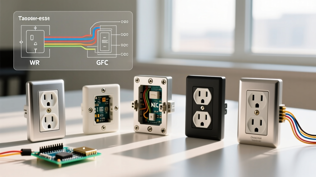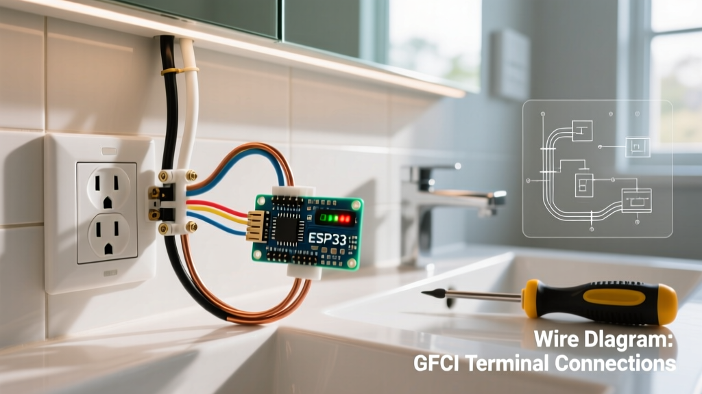

Understanding the Need for Receptacle Replacement
Many homeowners wonder how to replace electric outlet receptacles when they notice signs of wear, loose plug retention, or thermal discoloration. According to the National Fire Protection Association (NFPA), electrical distribution and lighting equipment are consistently among the leading causes of home structure fires. A degraded receptacle with loose internal contacts can arc, generating temperatures exceeding 1,000°F inside the wall cavity. This step-by-step guide moves beyond basic DIY advice, providing apprentice-level technical depth, exact torque specifications, and critical edge-case troubleshooting for standard 15A and 20A, 120V branch circuits.
Pre-Installation Diagnostics: When to Replace
Before breaking out the screwdriver, confirm that replacement is the correct intervention. Receptacles typically fail in three specific ways:
- Thermal Discoloration: If the thermoplastic face or the metal mounting yoke shows brown or black scorch marks, the internal brass contacts have degraded, creating high electrical resistance and excessive heat. Immediate replacement is mandatory.
- The Pull Test Failure: When a vacuum cleaner or lamp plug falls out of the receptacle under its own weight, the internal wiper contacts have lost their spring tension. This poor physical connection leads to micro-arcing every time a load is applied.
- Backstabbed Connections: Older installations often utilize push-in 'backstab' terminals rather than side-wiring. Over years of thermal cycling (heating and cooling), the internal spring clips fatigue and lose their grip on the copper wire, leading to open circuits or localized melting.
Tool and Material Matrix (2026 Pricing)
Using the correct tools ensures code compliance and personal safety. Below is the recommended loadout for a professional-grade receptacle swap.
| Tool / Material | Recommended Model | Est. Cost (2026) | Purpose |
|---|---|---|---|
| Non-Contact Voltage Tester | Fluke 2AC-II VoltAlert | $28.00 | Verifying dead circuit before touch |
| Wire Strippers | Klein Tools 11055 | $24.50 | Precision stripping for 14-10 AWG |
| Torque Screwdriver | Klein Tools 60172 | $115.00 | NEC 110.14(D) torque compliance |
| Tamper-Resistant Receptacle | Leviton 15A (R52-05320-00W) | $1.85 | Standard TR replacement device |
| 3-Light Receptacle Tester | Gardner Bender GRT-300 | $12.00 | Post-installation wiring verification |
Phase 1: Power Isolation and Verification
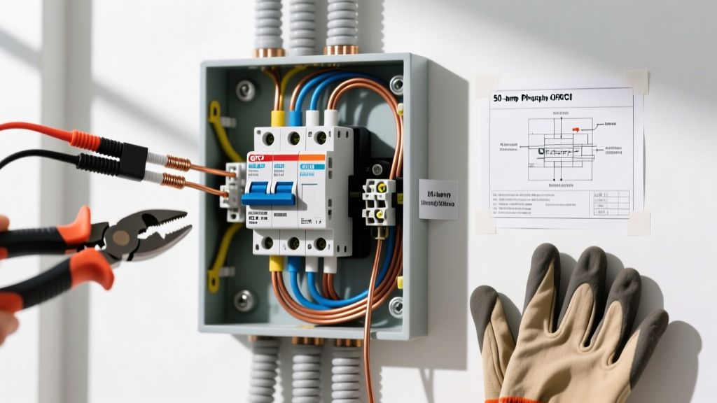
Safety begins at the panel. Identify the correct circuit breaker and switch it to the OFF position. While the OSHA electrical safety guidelines emphasize Lockout/Tagout (LOTO) procedures in commercial environments, residential DIYers must at minimum place a piece of painter's tape over the breaker with a note reading 'DO NOT TOUCH - WORK IN PROGRESS'.
Next, remove the faceplate and insert your Fluke 2AC-II into the top and bottom slots of the receptacle. The tip must remain dark and silent. Critical Step: Always test the NCVT on a known live circuit (like an adjacent room) before and after testing the target outlet to verify the tester's battery and internal circuitry are functioning correctly. A false negative from a dead tester is a leading cause of electrical shock.
Phase 2: Extraction and Wire Assessment
Remove the top and bottom mounting screws securing the yoke to the electrical box. Gently pull the receptacle out, being careful not to yank the wires. If the wires are backstabbed, you will need to release them. Insert a small flathead screwdriver or a dedicated release tool into the rectangular slot next to the wire to depress the internal spring clip, then pull the wire out. Never cut the wires flush with the back of the device unless you have ample slack in the box to re-strip them.
Once freed, inspect the copper conductors. If the wire ends are pitted, blackened, or deeply grooved from previous arcing, use your Klein 11055 strippers to cut back to fresh, shiny copper. Re-strip exactly 3/4 of an inch of insulation for standard side-wiring terminals. Ensure no bare copper is exposed outside the terminal block once seated, which could cause a short against the metal box.
Phase 3: The J-Hook Side-Wiring Method
Never use backstab terminals on a replacement receptacle, even if the new device supports them. Side-wiring provides a superior mechanical and electrical bond. Using needle-nose pliers, form a 'J-hook' at the end of your stripped wire. The hook must be shaped so that when the terminal screw is tightened, it pulls the loop closed rather than pushing it open.
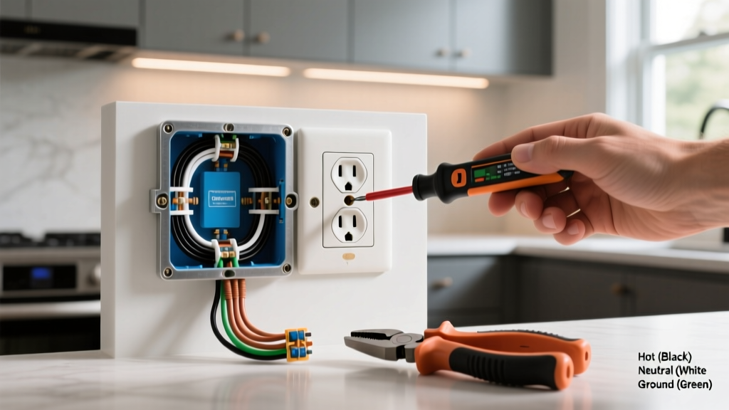
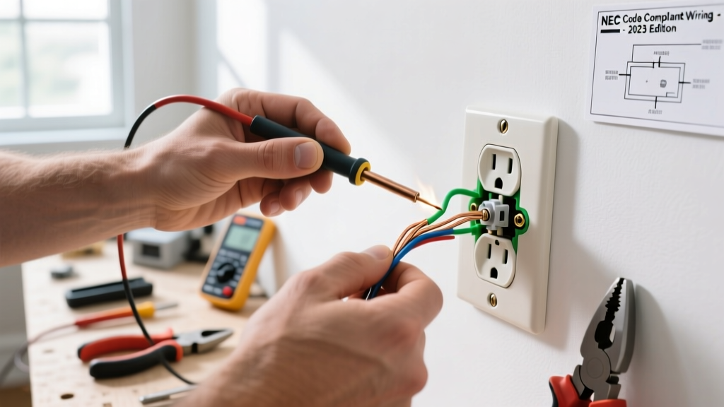
For standard North American wiring, the black (hot) wire connects to the brass screw, the white (neutral) wire connects to the silver screw, and the bare/green (ground) wire connects to the green grounding screw. Always loop the wire clockwise around the screw shaft. If you loop it counter-clockwise, the tightening action of the screw will push the wire out from under the screw head, resulting in a catastrophic high-resistance failure.
Pro Tip: When connecting the ground wire, leave it slightly longer than the hot and neutral wires. If the device is ever pulled forcefully from the box, the ground wire will be the last to disconnect, maintaining the safety path to earth for as long as possible.
Phase 4: Torqueing and Reinstallation
Since the 2017 NEC update, and reinforced in the 2023 and 2026 editions under section 110.14(D), covered equipment must be tightened to the manufacturer's specified torque using a calibrated torque tool. For standard 15A and 20A Leviton and Hubbell receptacles, the terminal screw torque specification is typically 14 in-lbs. Using a standard screwdriver and 'cranking it down' by feel often results in over-torquing, which strips the brass threads or shears the screw head, or under-torquing, which leaves a high-resistance connection prone to thermal runaway.
Set your Klein Tools 60172 torque screwdriver to 14 in-lbs, apply steady pressure until the tool clicks, and then fold the wires neatly into the back of the box. Use a 'Z-fold' technique, pushing the ground wire deep into the back corners first, followed by the neutral, and finally the hot wire, to avoid pinching the conductors against the sharp edges of the device yoke or the metal box ears.
Critical Edge Case: The Multi-Wire Branch Circuit (MWBC) Trap
One of the most lethal mistakes made when replacing a receptacle is failing to identify a Multi-Wire Branch Circuit (MWBC). An MWBC shares a single neutral wire between two hot wires on opposite phases (L1 and L2). If you open the shared neutral while the circuit is still partially energized, the neutral wire will carry the unbalanced return current, exposing you to 120V AC on what should be a grounded conductor.
Furthermore, if the hot tab on the receptacle is intact but the circuit feeds two separate breakers, you will create a direct phase-to-phase dead short (240V) the moment you turn the power back on, resulting in an explosive arc flash.
The Fix: Before extracting any receptacle, inspect the electrical panel. If you see two adjacent breakers tied together with a factory handle tie (required by NEC 210.4(B)) feeding the same room, you must turn off BOTH breakers. Always test all wires in the box with your Fluke 2AC-II, as the shared neutral will remain live if only one breaker is switched off. If replacing a split-receptacle (where the hot tab was previously broken to allow two separate circuits on one device), you must use wire nuts to pigtail the two hot wires to a single new hot wire if you are installing a standard single-circuit receptacle, or break the hot tab on the new device if maintaining the split configuration.
Final Testing and Code Compliance
Once the device is seated and the cover plate is secured, restore power at the panel. Use a 3-light receptacle tester, such as the Gardner Bender GRT-300, to verify correct wiring. The standard correct reading is two amber lights illuminated (indicating correct hot, neutral, and ground orientation). If you see a red light or a single amber light, you have reverse polarity, an open ground, or a hot/neutral reversal. Immediately cut power and re-verify your terminal connections.
Finally, perform a tamper-resistant (TR) verification. Attempt to insert a single non-pronged object (like a zip tie or a key) into one slot; the internal shutters should block entry, confirming the TR mechanism is functioning as mandated by NEC 406.12. For further reading on preventing electrical hazards in residential environments, consult the U.S. Consumer Product Safety Commission (CPSC) electrical safety guidelines. By adhering to these precise steps, you ensure a safe, code-compliant, and long-lasting electrical connection.