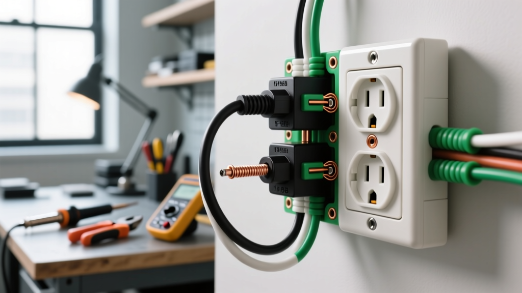

The Anatomy of a NEMA 5-15R Receptacle
When planning a residential or light-commercial wiring project, the 15 amp electrical outlet (technically designated as a NEMA 5-15R) is the most ubiquitous termination point you will encounter. Designed for 125V AC single-phase circuits, these receptacles are engineered to handle continuous loads up to 12 amps and non-continuous peak loads up to 15 amps. Despite their simplicity, improper termination remains a leading cause of residential electrical fires.
According to the National Fire Protection Association (NFPA), loose connections and improper wire stripping account for a significant percentage of receptacle-related thermal events. This reference guide provides exact wiring diagrams, National Electrical Code (NEC) compliance matrices, and professional termination specifications for 2026 installations.
Quick Spec Card: Standard 15A Duplex Outlet
- Voltage Rating: 125V AC
- Amperage Rating: 15A
- NEMA Designation: 5-15R (2-pole, 3-wire, grounding)
- Minimum Wire Gauge: 14 AWG Copper (12 AWG permitted and preferred for 20A circuits)
- Terminal Torque Spec: 14 in-lbs (UL 498 standard for #14/#12 AWG)
- Wire Strip Length: 5/8 inch (16mm) for side-wiring
Core Wiring Diagrams
Below are the two primary topologies for wiring a 15 amp electrical outlet. Always ensure the circuit breaker is locked out and tagged out (LOTO), and verify zero voltage with a CAT III or CAT IV multimeter before beginning.
Topology 1: End-of-Run (Single Feed)
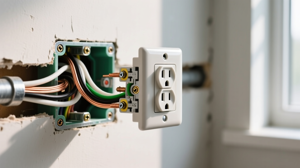
This configuration is used when the outlet is the final device on the branch circuit. Only one 14/2 or 12/2 NM-B (Romex) cable enters the single-gang electrical box.
- Hot (Line): Black wire from the NM-B cable terminates on the Brass screw terminal.
- Neutral: White wire from the NM-B cable terminates on the Silver screw terminal.
- Ground: Bare copper (or green) wire terminates on the Green grounding screw at the bottom of the yoke.
Pro-Tip: Always loop the wire clockwise around the screw terminal. As the screw tightens (righty-tighty), the clockwise loop will pull tighter around the screw shaft rather than splaying outward.
Topology 2: Middle-of-Run (Daisy-Chain / Parallel)
When the outlet is positioned between the breaker panel and downstream devices, two cables enter the box: a "Line" (feed from panel) and a "Load" (feed to next outlet).
NEC Article 250.148 mandates that the equipment grounding conductor must remain continuous. You cannot simply daisy-chain the ground wire through the receptacle's green screw, as removing the device would break the ground path for downstream outlets.
- Ground Pigtailing: Connect the bare ground from Cable 1 and Cable 2 together with a wire nut and a 6-inch bare copper pigtail. The pigtail connects to the outlet's green screw.
- Neutral Splice: Connect the white wires from both cables with a wire nut and a white pigtail to the silver screw. (Alternatively, use the back-wire clamp plates on commercial-grade receptacles to insert both neutral wires directly).
- Hot Splice: Connect the black wires from both cables with a wire nut and a black pigtail to the brass screw.
NEC Circuit Sizing & Receptacle Rating Matrix
A common point of confusion for DIYers and junior electricians is whether a 15 amp electrical outlet can be installed on a 20-amp breaker. The table below clarifies NEC Article 210.21(B)(3) requirements for multiplex (duplex) receptacles.
| Branch Circuit Rating | Permitted Receptacle Rating | Wire Gauge Required | Notes & Restrictions |
|---|---|---|---|
| 15 Amps | 15A Maximum | 14 AWG or 12 AWG | Cannot exceed circuit rating. |
| 20 Amps | 15A or 20A | 12 AWG Minimum | 15A duplex receptacles are legal on 20A circuits because the NEMA 5-15 plug limits single-device draw to 15A. |
| 30 Amps | 30A Only | 10 AWG Minimum | Standard 15A outlets strictly prohibited. |
Termination Methods: Backstab vs. Side-Wire vs. Back-Wire
The physical method used to terminate the wires at the 15 amp electrical outlet drastically impacts the longevity and safety of the connection.
1. Push-In (Backstab) Terminals
Found on cheap, builder-grade receptacles (like the basic Leviton 5320-WMP residential models). You strip the wire to 5/8" and push it into a hole in the back of the yoke, where a spring-loaded brass tang grips the wire.
- Pros: Fastest installation method.
- Cons: High failure rate. The spring tang loses tension over years of thermal expansion and contraction, especially under continuous 12A+ loads (e.g., space heaters, window AC units). This leads to arcing and melted plastic housings.
- Verdict: Avoid for any high-load or critical circuits.
2. Side-Wire (Screw Terminal)
The traditional method of wrapping the stripped wire around the brass or silver screw.
- Pros: Reliable, visual inspection is easy, no special tools required beyond a screwdriver.
- Cons: Time-consuming. If the wire is stripped too long, exposed copper creates a short-circuit hazard. If the loop is bent counter-clockwise, the screw pushes the wire out.
- Verdict: Excellent for standard residential work when done meticulously.
3. Back-Wire (Screw-Clamp)
Found on commercial-spec and hospital-grade receptacles (e.g., Hubbell 5262 or Leviton 5362). You insert the straight-stripped wire into a rear hole, and tightening the side screw pulls a heavy-duty steel clamp plate down onto the wire.
- Pros: Extremely secure. Accepts both 14 and 12 AWG wire. Allows two wires per terminal (one on each side of the clamp). Eliminates the risk of exposed copper shiners.
- Cons: Receptacles cost roughly $3.50 to $6.00 each, compared to $1.25 for builder-grade.
- Verdict: The absolute best practice for 2026 electrical installations.
Box Fill Calculations for Single-Gang 15A Outlets
Overcrowding an electrical box causes wire insulation damage and traps heat. Per NEC Article 314.16, you must calculate box fill before installing your 15 amp electrical outlet.
Scenario: A middle-of-run outlet with two 14/2 NM-B cables entering a single-gang plastic box.
- Current-Carrying Conductors: 2 Blacks + 2 Whites = 4 wires. (14 AWG multiplier is 2.0 cu in). Total: 8.0 cu in.
- Equipment Grounds: All bare/green wires count as a single volume allowance based on the largest ground. Total: 2.0 cu in.
- Device (Receptacle): The yoke counts as 2 volume allowances based on the largest wire connected. Total: 4.0 cu in.
- Cable Clamps: Internal plastic box clamps count as 0. (If using a metal box with internal clamps, add 2.0 cu in).
Total Required Volume: 14.0 cubic inches. A standard 18 cu in or 22 cu in single-gang "old work" or "new work" box will safely accommodate this setup.
Troubleshooting Common 15A Receptacle Failures
When an outlet fails or trips a breaker, use this diagnostic matrix before replacing the device.
| Symptom | Probable Cause | Corrective Action |
|---|---|---|
| GFCI trips immediately upon plugging in a device | Bootleg ground (neutral and ground jumpered together at the outlet) or a true ground fault in the appliance. | Remove neutral-to-ground jumper. Test appliance on a known good circuit. |
| Downstream outlets are dead, but the tested outlet works | Backstab push-in connection failed on the "Load" side of the tested outlet due to thermal fatigue. | Replace the upstream outlet and transition all backstab connections to side-wire or back-wire clamps. |
| Receptacle faceplate is warm to the touch | Loose terminal screw causing high resistance, or circuit is overloaded beyond 15A continuous. | Check amp draw with a clamp meter. Retorque terminal screws to 14 in-lbs. |
Safety and Code Compliance References
Electrical work is inherently hazardous. The U.S. Consumer Product Safety Commission (CPSC) emphasizes that all 15A and 20A receptacles installed in residential dwellings must be Tamper-Resistant (TR) to prevent childhood shock injuries. Furthermore, the Occupational Safety and Health Administration (OSHA) strictly enforces Lockout/Tagout (LOTO) procedures for any commercial or industrial termination work. Always consult your local Authority Having Jurisdiction (AHJ) regarding AFCI and GFCI requirements, as local amendments frequently supersede baseline NEC guidelines for kitchen, bathroom, and outdoor 15 amp electrical outlet placements.