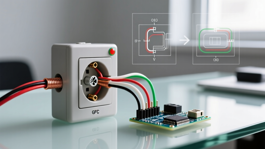

The Anatomy of a Dead Receptacle: Wiring Diagram Breakdown
When a standard 120V duplex receptacle suddenly loses power, the immediate assumption is often a failed outlet. However, from a wiring diagram perspective, the receptacle itself (such as a standard Leviton T5320-W 15A tamper-resistant model) is rarely the point of failure. Instead, the issue almost always lies in the termination points, the upstream daisy-chain, or a hidden ground-fault interruption. Understanding what causes an electrical outlet to stop working requires reading the physical wiring as a schematic: tracing the line (hot), load (downstream hot), neutral, and equipment grounding conductor paths.
A standard 15A or 20A branch circuit relies on continuous metallic continuity. The brass screws represent the ungrounded (hot) conductors, the silver screws represent the grounded (neutral) conductors, and the green screw is the equipment ground. When power drops, we must systematically isolate whether the fault is on the line side (power coming from the panel) or the load side (power passing to downstream devices).
Top 5 Causes of Outlet Failure (Traced via Wiring Diagrams)
1. Backstab (Push-In) Connection Failure
The most frequent culprit in dead outlets is the failure of push-in (backstab) wire terminations. Inside the receptacle, these connections rely on a small brass leaf spring to grip 14 AWG solid copper wire. Over years of thermal cycling—especially when running high-draw appliances like space heaters or hair dryers—the spring loses its metallurgical temper. The wire expands and contracts, eventually working loose and creating a high-resistance arc or a complete open circuit. Expert Fix: Never use backstab connections. Strip the wire to 3/4 inch and loop it clockwise around the brass/silver terminal screws, torquing to the manufacturer's specification (typically 14 in-lbs for standard 15A/20A receptacles).
2. Broken Daisy-Chain (Load Side Interruption)
Modern residential wiring often daisy-chains multiple outlets on a single 15A or 20A breaker. If Outlet A is wired to feed Outlet B via its "LOAD" terminals, a loose neutral or hot wire on Outlet A's load side will kill power to Outlet B, even if Outlet A appears to be working. When reviewing the wiring diagram, always check both the LINE and LOAD terminal pairs on upstream receptacles.
3. Tripped GFCI Upstream
Per recent NEC updates, Ground Fault Circuit Interrupter (GFCI) protection has been vastly expanded. A standard, non-GFCI outlet in a living room, hallway, or garage may actually be wired downstream of a GFCI receptacle located in a bathroom, kitchen, or exterior wall. If the upstream GFCI trips due to a minor leakage current (as low as 4-6mA), all downstream standard outlets will stop working. Always map your circuit's GFCI hierarchy before tearing apart drywall.
4. Loose Neutral at the Panel or Junction
A floating or loose neutral is a dangerous fault condition. If the neutral bus bar connection at the main service panel is loose, or if a neutral wire nut in an attic junction box has vibrated free, the circuit loses its return path to the source. Symptoms include outlets measuring anywhere from 0V to 240V depending on the load imbalance across the split-phase panel. This requires immediate verification with a True-RMS multimeter.
5. Melted Pigtail or Wire Nut Failure
In older homes, or where DIYers have overloaded a junction box, the wire nuts connecting the pigtails to the main branch circuit wires can fail. If a wire nut is not twisted tight enough to twist the wires themselves, the connection relies solely on the metal insert. Under a 15A continuous load, this high-resistance joint will generate heat, melt the thermoplastic insulation, and eventually open the circuit. The U.S. Consumer Product Safety Commission (CPSC) frequently cites improper wire splicing as a leading cause of residential electrical fires.
Diagnostic Matrix: Symptom vs. Wiring Fault
| Observed Symptom | Multimeter Reading (Hot to Neutral) | Multimeter Reading (Hot to Ground) | Probable Wiring Diagram Fault |
|---|---|---|---|
| Completely dead outlet | 0.0V | 0.0V | Open Line (Hot) conductor; tripped breaker or upstream backstab failure. |
| Outlet dead, but voltage present | 0.0V - 10.0V | 120.0V | Open Neutral conductor; broken load-side neutral daisy-chain. |
| Half-hot (switched) outlet dead | 0.0V (Top), 120V (Bottom) | 0.0V (Top), 120V (Bottom) | Broken tab on brass (hot) side not removed, or wall switch failure. |
| Phantom voltage detected | 40.0V - 90.0V | 120.0V | Induced voltage from parallel runs; broken neutral or high-resistance splice. |
Step-by-Step Multimeter Tracing Protocol
To accurately determine what causes an electrical outlet to stop working without guessing, follow this systematic isolation protocol using a True-RMS multimeter (such as the Fluke 117) and a non-contact voltage tester (NCVT).
- Verify Line Voltage (Hot to Ground): Set your multimeter to AC Voltage. Insert the black probe into the ground (U-shaped slot) and the red probe into the hot (shorter vertical slot). A reading of 115V-125V confirms power is reaching the receptacle's line side. If 0V, the fault is upstream (breaker, GFCI, or severed cable).
- Check Neutral Integrity (Neutral to Ground): Move the red probe to the neutral slot (longer vertical slot). The reading should be very close to your Hot-to-Ground reading (within 2V). If you read 120V Hot-to-Ground but 0V Hot-to-Neutral, you have an open neutral fault.
- Load Side Continuity Test: If the dead outlet is wired as a pass-through, turn off the breaker, remove the receptacle, and set the multimeter to Continuity/Ohms. Test the black load wire against the known hot line wire (with wires disconnected and safely separated). Trace the physical wiring diagram to the next downstream box to locate the break.
⚠️ Safety Warning: Never assume a circuit is dead based solely on a non-contact voltage tester. NCVTs can yield false negatives due to shielded cables or false positives due to phantom voltage. Always verify with a calibrated digital multimeter before touching bare conductors. For comprehensive safety standards, refer to the National Fire Protection Association (NFPA) NEC guidelines.
Code Compliance & Repair Standards (NEC 2026 Updates)
When repairing a dead outlet, your fix must comply with the latest National Electrical Code (NEC). The 2026 NEC continues to enforce strict rules on termination torque and ground-fault protection:
- Torque Verification (NEC 110.14(D)): Electricians are required to use calibrated torque screwdrivers to secure terminal screws. Hand-tightening is no longer code-compliant for new installations or major repairs, as it leads to the exact thermal failures that cause outlets to die prematurely.
- Expanded AFCI/GFCI Protection: If you are replacing a dead outlet in a kitchen, bathroom, garage, or outdoor location, the NEC mandates GFCI protection. If the circuit is a 120V, single-phase, 15A or 20A branch circuit supplying a living area, Arc-Fault Circuit Interrupter (AFCI) protection is also required at the breaker panel.
- Tamper-Resistant (TR) Mandate: All 15A and 20A receptacles installed in dwelling units must be TR type to prevent foreign object insertion. Standard non-TR receptacles are obsolete for residential replacement.
For more on maintaining a safe home electrical infrastructure, the U.S. Department of Energy provides excellent baseline guidelines on residential electrical system upkeep and energy efficiency.
Frequently Asked Questions
Why did my outlet stop working after plugging in a vacuum cleaner?
Vacuum cleaners draw high startup current (often 12-14 amps). If your outlet is wired using backstab connections, this sudden surge can cause a weak internal spring to arc and permanently lose contact. It may also have tripped an upstream AFCI breaker due to the motor's electrical noise.
Can a bad ground wire cause an outlet to stop working?
No. The equipment grounding conductor (bare copper or green) is a safety path for fault currents and carries no current during normal operation. A broken ground will not interrupt the flow of electricity to your devices, though it creates a severe shock hazard and leaves the circuit unprotected in the event of a short.
How much does it cost to rewire a dead outlet?
If the issue is a simple backstab failure or loose wire nut at the receptacle, a DIY repair costs under $15 for a new TR receptacle and wire connectors. If a licensed electrician is required to trace a broken wire inside the drywall or replace a damaged cable run, expect to pay between $150 and $350 in 2026, depending on local labor rates and drywall repair requirements.


