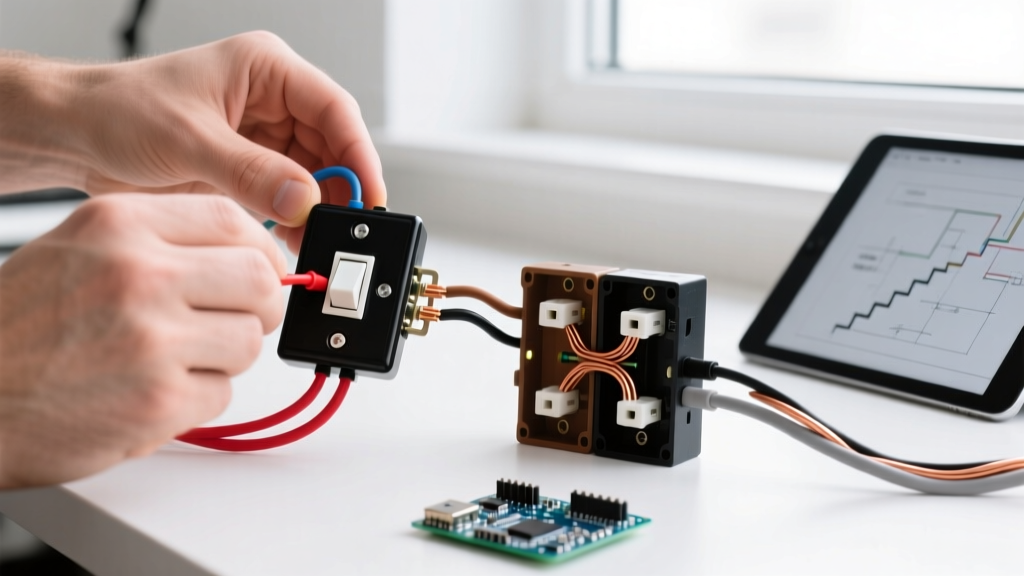

The Terminology Trap: What Does '2-Way' Actually Mean?
When DIYers and apprentice electricians search for a wiring diagram for a 2 way light switch, they frequently fall into a dangerous geographical terminology trap. Depending on where you live, a '2-way switch' refers to two completely different electrical circuits. In North America, a standard wall switch with two terminals is called a single-pole switch, though beginners often mistakenly call it a 2-way switch because it has two primary wire connections. Conversely, in the UK, Australia, and regions following IEC standards, a '2-way switch' refers to a staircase or hallway circuit where two separate switches control a single light fixture—what North Americans call a 3-way switch.
Wiring the wrong diagram for your region's hardware will result in tripped breakers, fried smart-switch logic boards, or severe shock hazards. This guide breaks down both scenarios with exact terminal specifications, cable gauges, and code requirements to ensure your installation is safe and functional.
CRITICAL SAFETY WARNING: Before removing any faceplate, shut off the circuit at the main distribution board. Verify the circuit is dead using a non-contact voltage tester (NCVT) like the Fluke 1AC-II VoltAlert and a multimeter. Never rely solely on a wall switch to isolate power.
Scenario A: The North American 'Single-Pole' (2-Terminal) Switch
If you are in the US or Canada and simply want one switch to control one light from one location, you need a single-pole switch. A standard model like the Leviton Decora 5601 or Lutron Diva DV-103P features two main terminal screws (excluding the ground).
Standard US Single-Pole Wiring Flow
- Identify the Cables: You will typically have one 14/2 NM-B (Romex) cable bringing power from the panel (Line) and one 14/2 cable going to the light fixture (Load). Note: If the circuit is rated for 20 Amps, you must use 12 AWG wire and a 12/2 cable.
- Prepare the Wires: Strip exactly 3/4 inch of insulation using precision strippers like the Klein Tools 11055. Over-stripping exposes bare copper outside the terminal, creating a short-circuit risk.
- Connect the Ground: Wrap the bare copper ground wire clockwise around the green grounding screw on the switch and tighten to 12 in-lbs of torque.
- Terminate Line and Load: Connect the black (hot) Line wire to one brass terminal, and the black Load wire to the other brass terminal. For standard mechanical single-pole switches, polarity between the two brass screws does not matter. However, if you are installing a smart switch (e.g., Leviton Decora Smart DW15S), the Line and Load must be identified correctly, and a neutral (white) wire connection is mandatory.
- Cap the Neutrals: In a standard mechanical switch box, the white neutral wires from the Line and Load cables bypass the switch and are joined together with a wire nut (e.g., Ideal WireNuts 72B).
Scenario B: The International 2-Way (Staircase) Circuit
If you are in the UK, Australia, or Ireland, a '2-way lighting circuit' allows you to control a light from two locations (e.g., the top and bottom of a staircase). In North America, this exact same topology is achieved using '3-way switches'. The hardware features three primary terminals: COM (Common), L1, and L2.
Component & Wire Specification Matrix
| Feature | US Single-Pole (Misnamed 2-Way) | UK/AUS 2-Way (US 3-Way) |
|---|---|---|
| Terminal Count | 2 (Plus Ground) | 3 (COM, L1, L2) Plus Earth |
| Standard Cable | 14/2 or 12/2 NM-B (Romex) | 1.5mm² 3-Core & Earth (BS 6004) |
| Traveler Wires | N/A | 2 (L1 and L2 Strappers) |
| Common Switch Model | Lutron Diva DV-103P | MK Logic Plus 10AX (K900WHI) |
| Governing Code | NEC Article 404 (NFPA 70) | BS 7671 (IET Wiring Regs) |
Step-by-Step Installation: International 2-Way Traveler Method
For this scenario, we will wire a traditional 2-way circuit using 1.5mm² 3-core and earth cable. Switch 1 is at the bottom of the stairs (receiving mains power), and Switch 2 is at the top (sending power to the ceiling rose).
Switch 1 (Power Source Location)
- Line In: Connect the permanent live (Brown) from the mains supply to the COM terminal.
- Strappers (Travelers): Connect the Brown and Black (with brown sleeve) wires of the 3-core cable to the L1 and L2 terminals. The order of L1 and L2 does not affect functionality, but keeping them consistent aids future troubleshooting.
- Neutral Bypass: Connect the blue neutral from the mains supply directly to the blue neutral heading to the light fixture using a Wago 221 lever nut. The switch never interrupts the neutral.
Switch 2 (Light Fixture Location)
- Switched Live Out: Connect the COM terminal to the live wire heading up to the light fixture.
- Strappers (Travelers): Connect the corresponding L1 and L2 wires from the 3-core cable to the L1 and L2 terminals on Switch 2.
- Earth (Ground): Sleeve all bare earth wires with green/yellow PVC sleeving and terminate them to the earth terminal block in the backbox and the switch faceplate (if metal).
Common Failure Modes and Edge Cases
Even with a perfect wiring diagram for a 2 way light switch on hand, field conditions often introduce errors. Here are the most common failure modes we diagnose at ElectricalFlux:
1. The 'Neutral Switching' Hazard
A dangerous mistake made by novices is switching the neutral wire instead of the live/hot wire. This occurs when the permanent live is wired directly to the light, and the switch interrupts the neutral return path. Result: The light turns on and off correctly, but the light fixture remains permanently energized at full mains voltage. Changing a bulb in this state poses a lethal shock risk. Always verify that the switch interrupts the Line/Hot conductor.
2. Traveler (Strapper) Cross-Wiring
In a 2-way/3-way circuit, if you accidentally wire the COM terminal on Switch 1 to an L1/L2 terminal on Switch 2, the circuit will exhibit 'ghost' behavior. The light will only turn on if Switch 1 is in a specific position, rendering Switch 2 useless or reversing its logic. Use a continuity tester to map the 3-core traveler cable before terminating.
3. Smart Switch Incompatibility
Upgrading a UK 2-way circuit to smart switches (like the Shelly Plus 1 or Sinope RM3500ZB) requires fundamentally altering the wiring. Smart switches require a constant live and a neutral at the switch location to power their internal Wi-Fi/Zigbee radios. Traditional 2-way circuits often lack a neutral at the secondary switch. In these cases, you must use a wireless secondary switch (e.g., Shelly Plus i4) or re-pull a 4-core cable to provide a neutral.
Code Compliance and Safety Standards
Adhering to regional electrical codes is not just a legal requirement; it ensures your insurance remains valid in the event of an electrical fire. In North America, switch installations are governed by NFPA 70 (The National Electrical Code), specifically Article 404, which mandates that all switch loops must now include a grounded (neutral) conductor at the switch box to accommodate modern energy-management devices.
In the UK and regions following the IET standards, installations must comply with BS 7671 (The 18th Edition Wiring Regulations). A key requirement under BS 7671 is the strict color-coding of strappers (travelers) and the mandatory use of green/yellow sleeving on all exposed earth conductors. Furthermore, OSHA electrical safety guidelines and international equivalents mandate that all metal switch plates be properly earthed (grounded) to prevent the faceplate from becoming energized in the event of an internal fault.
Final Verification Checklist
Before restoring power to the breaker panel, complete this physical inspection:
- Tug Test: Gently pull on every terminated wire to ensure it is securely clamped by the terminal screw or lever nut.
- Insulation Check: Verify that no bare copper is visible outside the terminals and that no wire insulation is pinched under the terminal screws.
- Box Dressing: Neatly fold the wires into the backbox in a Z-pattern. Forcing the switch into a crowded box can cause the ground wire to slip off the green screw, creating an ungrounded metal faceplate.
By understanding the distinct regional definitions and following the precise terminal mappings outlined above, you can confidently execute any wiring diagram for a 2 way light switch, ensuring a safe, code-compliant, and reliable lighting circuit.


