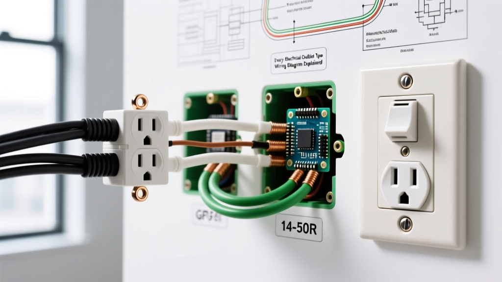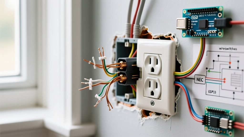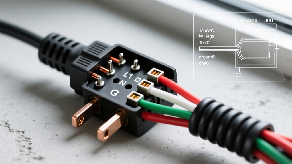

Decoding the 30-Amp Receptacle Landscape
When searching for a reliable wiring diagram for 30 amp plug configurations, the most common mistake DIYers make is assuming all 30-amp outlets are identical. In reality, the National Electrical Manufacturer Association (NEMA) defines several distinct 30-amp configurations, each serving drastically different voltage requirements and use cases. Miswiring a 120V RV receptacle with 240V dryer power will instantly destroy sensitive onboard electronics, while failing to isolate the neutral and ground on a modern dryer circuit violates critical safety codes.
This guide breaks down the three most common 30-amp wiring scenarios you will encounter in residential and light-commercial settings: the RV park hookup (NEMA TT-30), the modern electric dryer (NEMA 14-30), and the portable generator inlet (NEMA L14-30). We will provide exact terminal assignments, torque specifications, and 2026 material considerations to ensure your installation is both functional and compliant with the latest NFPA 70 (National Electrical Code) standards.
NEMA 30-Amp Configuration Matrix
Before stripping any wire insulation, you must verify the NEMA configuration stamped on the face of your receptacle. Use the comparison matrix below to identify your specific hardware.
| NEMA Code | Configuration | Voltage | Prongs | Primary Application |
|---|---|---|---|---|
| TT-30 | Travel Trailer | 125V AC | 3-Prong | RV Park Receptacles, Campgrounds |
| 14-30 | Straight Blade | 125/250V AC | 4-Prong | Modern Electric Dryers, Kilns |
| L14-30 | Twist-Lock | 125/250V AC | 4-Prong | Generator Inlets, Transfer Switches |
Scenario A: The RV Receptacle (NEMA TT-30)
The NEMA TT-30 is uniquely designed for the recreational vehicle industry. Despite its physical resemblance to older 240V dryer plugs, it is strictly a 120-volt, single-phase circuit. According to NEC Article 551.46, RV receptacles must be grounded and properly polarized.
Step-by-Step Wiring Flow
- Breaker Selection: Install a 30A single-pole breaker in your main or sub-panel.
- Cable Preparation: Use 10/2 AWG NM-B (Romex) with a bare copper ground. Strip the outer jacket, leaving 1/4 inch of sheathing inside the gang box.
- Wire Stripping: Strip exactly 5/8 inch of insulation from the black (hot), white (neutral), and bare (ground) wires.
- Terminal Assignment:
- Hot (Black): Connect to the brass terminal marked 'X'.
- Neutral (White): Connect to the silver terminal marked 'W'.
- Ground (Bare): Connect to the green grounding screw marked 'G'.
- Torque Verification: Using a calibrated torque screwdriver, tighten the terminal screws to the manufacturer's specification (typically 14-18 in-lbs for Leviton and Hubbell 30A devices). Loose connections cause arcing and thermal failure.
CRITICAL WARNING: Never wire a TT-30 receptacle to a double-pole 240V breaker. Applying 240V across the Hot (X) and Neutral (W) terminals will immediately fry the RV's power converter, air conditioning units, and entertainment systems.
Scenario B: Electric Dryer Modernization (NEMA 14-30)
If you are upgrading an older home from a 3-prong (NEMA 10-30) to a modern 4-prong (NEMA 14-30) dryer outlet, you are dealing with a 125/250V circuit. The transition to the 14-30 configuration was mandated by the NEC to eliminate the dangerous practice of bonding the appliance frame to the neutral wire.
Wiring the 4-Prong Receptacle
You must run 10/3 AWG copper cable from a 30A double-pole breaker. This cable contains Black (Hot 1), Red (Hot 2), White (Neutral), and Bare (Ground).
- X Terminal (Brass): Connect Black wire (120V Leg 1).
- Y Terminal (Brass): Connect Red wire (120V Leg 2).
- W Terminal (Silver): Connect White wire (Dedicated Neutral).
- G Terminal (Green): Connect Bare wire (Equipment Grounding Conductor).
Edge Case Troubleshooting: If your older panel lacks a dedicated neutral bus bar and the ground/neutral are bonded (which is only permitted on the main service disconnect), you must consult a licensed electrician to separate the ground and neutral bars in a sub-panel before installing a 14-30 receptacle. Mixing them on a sub-panel creates parallel neutral paths, violating OSHA electrical safety guidelines and NEC Article 250.142.
Scenario C: Generator Inlet & Transfer Switch (NEMA L14-30)
The NEMA L14-30 twist-lock plug is the gold standard for portable generators in the 7,500-watt to 8,500-watt range. Wiring this inlet requires strict adherence to anti-backfeed regulations to protect utility workers.
Transfer Switch Integration
You cannot wire an L14-30 inlet directly to a breaker panel. It must feed into a Manual Transfer Switch (MTS) or an approved breaker interlock kit. According to FEMA and Ready.gov generator safety protocols, backfeeding the grid through a main breaker is illegal and highly lethal.
- Inlet Placement: Mount the L14-30 inlet box (e.g., Reliance Controls PB30) on the exterior of the home, at least 5 feet away from any operable window or door to prevent carbon monoxide intrusion.
- Conduit & Wiring: Run four individual THHN/THWN-2 wires (Black, Red, White, Green) inside 3/4-inch PVC conduit from the inlet box to the interior transfer switch.
- Terminal Mapping: Match the L14-30 inlet pins to the MTS input terminals: X (Hot 1), Y (Hot 2), W (Neutral), G (Ground).
2026 Material Costs & Component Selection
Electrical material costs have stabilized following the supply chain disruptions of the early 2020s, but copper prices remain a factor in long wire runs. Below is a realistic pricing breakdown for a standard 30-amp installation in 2026.
| Component | Recommended Brand/Model | Estimated 2026 Cost |
|---|---|---|
| 10/2 NM-B Cable (250ft roll) | Southwire / Cerrowire | $210.00 - $245.00 |
| 10/3 NM-B Cable (250ft roll) | Southwire / Cerrowire | $340.00 - $390.00 |
| TT-30R Receptacle | Leviton 278-S00 | $14.50 - $18.00 |
| 14-30R Receptacle | Hubbell 9430FR | $22.00 - $28.00 |
| L14-30 Inlet Box | Reliance Controls PB30 | $55.00 - $75.00 |
| 30A Double-Pole Breaker | Square D Homeline / QO | $12.00 - $18.00 |
Voltage Drop Calculations for Long Runs
A frequently overlooked aspect of 30-amp wiring is voltage drop over distance. The NEC recommends a maximum 3% voltage drop for branch circuits. If you are running a 120V TT-30 circuit to an RV pad at the back of a property, 10 AWG copper wire may be insufficient for long distances.
Using the standard voltage drop formula VD = (2 x K x I x L) / CM (where K=12.9 for copper, I=30A, L=length in feet, CM=10,380 circular mils for 10 AWG):
- At 50 feet (120V TT-30): Voltage drop is ~3.7V (3.1%). This is on the absolute edge of acceptable limits.
- At 100 feet (120V TT-30): Voltage drop is ~7.4V (6.2%). This will cause RV air conditioners to stall and overheat.
The Fix: If your RV pedestal run exceeds 60 feet on a 120V system, you must upsize your conductors to 8 AWG copper or 6 AWG aluminum to maintain safe voltage delivery to the RV's surge protector and appliances.
Summary of Critical Failure Modes
Before energizing any 30-amp circuit, perform a final continuity and polarity check with a digital multimeter. Watch for these specific failure modes:
- Bootleg Grounds: Testing between Neutral (W) and Ground (G) shows 0 ohms on a 14-30 receptacle. This indicates the neutral and ground are illegally bonded at the receptacle rather than at the main panel.
- Reversed Polarity on TT-30: Testing Hot to Ground reads 0V, while Neutral to Ground reads 120V. The hot and neutral wires were swapped at the terminal block, creating a severe shock hazard for anyone touching the RV chassis.
- Thermal Creep: If using stranded THHN wire in a receptacle designed for solid wire, the strands can flatten over time under screw pressure, leading to a loose connection, high resistance, and eventual melting of the receptacle face. Always use crimp-on pin terminals if the device manufacturer specifies it for stranded wire.