
The Critical Intersection of High-Amperage Wiring and NEC Compliance
Installing a 50-amp receptacle is one of the most demanding residential electrical projects a DIYer or journeyman can undertake. Whether you are setting up a NEMA 14-50R for an RV pedestal, a Level 2 Electric Vehicle Supply Equipment (EVSE) charger, or a heavy-duty MIG welder, the margin for error is zero. A poorly executed 50-amp circuit doesn't just trip breakers; it generates catastrophic arc faults, melts insulation, and ignites structural fires.
This comprehensive safety guide and code compliance manual provides the exact wiring diagram for 50 amp plug configurations, breaking down National Electrical Code (NEC) mandates for wire sizing, torque specifications, and Ground Fault Circuit Interrupter (GFCI) requirements. As we navigate the 2026 electrical landscape, adherence to NEC Articles 210, 250, and 310 is not optional—it is the baseline for life safety.
Decoding NEMA Configurations: 14-50R vs. 6-50R
Before pulling any wire, you must identify the correct NEMA (National Electrical Manufacturers Association) configuration. The two most common 50-amp receptacles are the NEMA 14-50R and the NEMA 6-50R. Confusing these two is a primary cause of equipment destruction and code violations.
| Feature | NEMA 14-50R (4-Prong) | NEMA 6-50R (3-Prong) |
|---|---|---|
| Voltage | 125/250V (Split-Phase) | 250V (Straight-Phase) |
| Wire Count | 4 Wires (Hot, Hot, Neutral, Ground) | 3 Wires (Hot, Hot, Ground) |
| Neutral Required? | Yes (White/Grey) | No |
| Common Applications | RV Hookups, EV Chargers, Electric Ranges | Welders, Plasma Cutters, Air Compressors |
| NEC Neutral Rule | Must be insulated, sized equal to hots | Neutral bar not connected to receptacle |
Code Alert: Under NEC Article 250.140, you can no longer use the equipment grounding conductor as a neutral return path for new installations. If your appliance requires 120V logic (like an RV or EV charger), you must install a 4-wire 14-50R circuit.
Wire Sizing and Breaker Selection: NEC Table 310.15(B)(16)
The most frequent failure point in high-amperage DIY wiring is undersized conductors. A 50-amp circuit demands precise wire gauging based on the conductor material and insulation temperature rating.
Copper vs. Aluminum Conductors
- 6 AWG Copper (THHN/THWN-2): Rated for 65 amps in the 90°C column, but NEC 110.14(C) requires us to use the 75°C column for termination limits. In the 75°C column, 6 AWG copper is rated for exactly 65 amps, making it perfectly safe and code-compliant for a 50-amp breaker.
- 4 AWG Aluminum (XHHW-2): Aluminum is highly cost-effective for long runs. However, 6 AWG aluminum is only rated for 50 amps at 75°C, leaving zero headroom for voltage drop or thermal derating. Always upsize to 4 AWG aluminum (rated 65A at 75°C) for 50-amp circuits to ensure safety and compliance.
The Voltage Drop Multiplier
If your receptacle is located more than 50 feet from the main service panel, NEC recommends limiting voltage drop to 3% for branch circuits. For a 50-amp load over 75 feet, you must upsize to 4 AWG Copper or 2 AWG Aluminum to prevent the EV charger or welder from browning out and damaging internal logic boards.
Visualizing the Wiring Diagram for 50 Amp Plug Connections
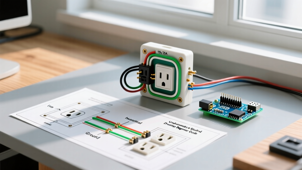
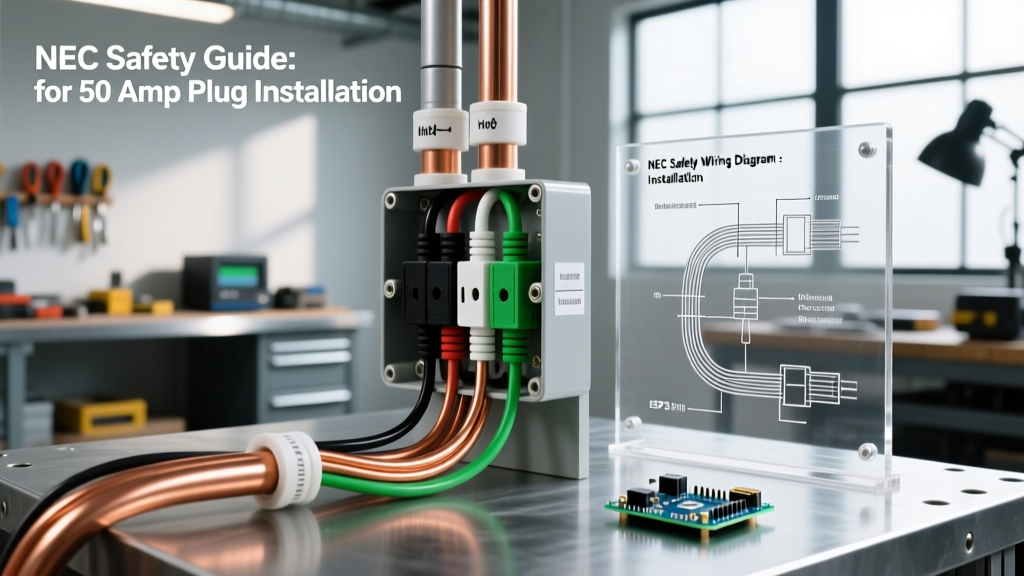
Because physical space and orientation vary by manufacturer (e.g., Leviton 278-S00 vs. Hubbell 9450A), relying on a static image can lead to miswiring. Instead, use this terminal-mapping diagram matrix for the industry-standard NEMA 14-50R receptacle. Always verify the physical stamping on your specific device.
| Receptacle Pin / Terminal | Wire Color (NEC Std) | Breaker Connection | Function |
|---|---|---|---|
| X (Left Hot) | Black | Pole 1 (50A Double-Pole) | 120V Leg A |
| Y (Right Hot) | Red | Pole 2 (50A Double-Pole) | 120V Leg B |
| W (Neutral) | White (or Grey) | Panel Neutral Bar | 120V Return Path |
| G (Ground) | Green or Bare Copper | Panel Ground Bar | Fault Current Path |
Note: For a NEMA 6-50R (Welder), the White Neutral wire is omitted entirely. The Ground pin connects to the panel ground bar, and the two Hots connect to the double-pole breaker.
The Torque Mandate: NEC 110.14(D) Compliance
Since the 2017 NEC cycle, and strictly enforced through 2026, Article 110.14(D) requires that all electrical terminations be torqued to the manufacturer's specified values using a calibrated torque tool. Hand-tightening a 50-amp receptacle by 'feel' is a direct code violation and a massive fire hazard.
Step-by-Step Termination Protocol
- Strip the Wire: Remove exactly 3/4 inch of insulation. Do not nick the copper or aluminum strands.
- Prep Aluminum (If Applicable): If using aluminum wire, brush the exposed strands with a wire brush and apply an antioxidant paste like Gardner Bender GAO-52TZ to prevent aluminum oxide buildup, which increases resistance and heat.
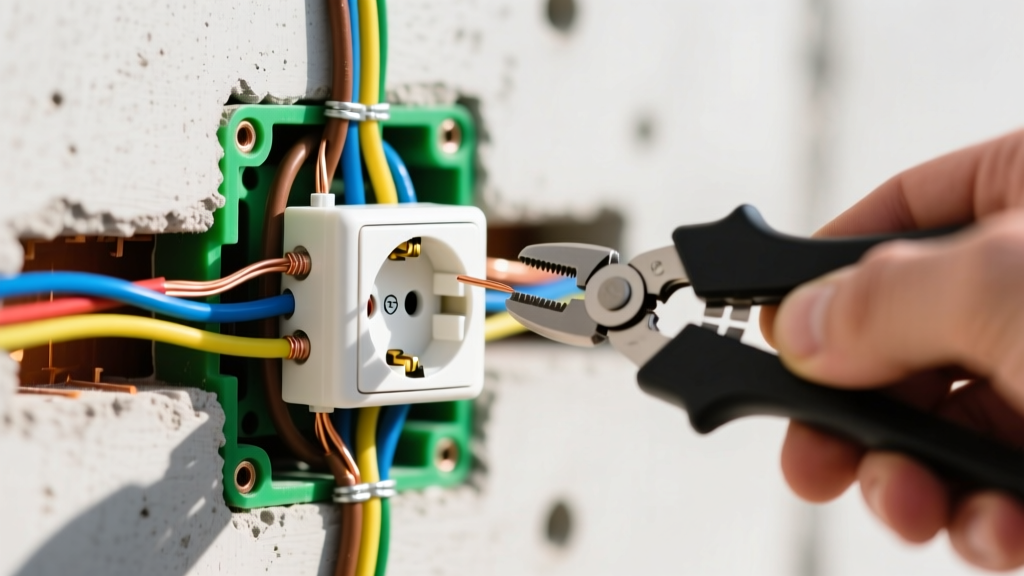
- Seat the Wire: Insert the wire fully into the receptacle lug. Ensure no bare wire is exposed outside the terminal, and no insulation is trapped under the pressure plate.
- Apply Torque: Using a calibrated torque screwdriver (e.g., Klein Tools VDV110-001), tighten the set screw. For a standard Hubbell 9450A 50-amp receptacle, the manufacturer specifies 45 in-lbs of torque. For Leviton models, verify the stamp on the yoke, which typically ranges between 35 to 50 in-lbs.
GFCI Protection and the EV Charging Dilemma
The most significant shift in recent NEC cycles (2020, 2023, and 2026) regarding 50-amp receptacles is the mandate for GFCI protection. Under NEC 210.8(F), all 50-amp receptacles installed in residential garages, basements, and outdoors must be GFCI protected.
The Nuisance Tripping Issue
Many modern EV chargers (EVSEs) have internal ground-fault detection that conflicts with the 50-amp GFCI breaker in the main panel, causing nuisance tripping. Furthermore, the U.S. Department of Energy notes that continuous plugging and unplugging of heavy 50-amp EV cords degrades receptacle tension over time, increasing arc-flash risks.
The Code-Compliant Solution: If you are installing a dedicated circuit solely for an EV charger in a garage, the safest and most reliable method is to hardwire the EVSE directly to a junction box. Hardwired EVSEs do not require a receptacle, thereby bypassing the 210.8(F) GFCI receptacle mandate (though the EVSE itself provides the required personnel protection). If you must use a plug for flexibility, you are required to install a 50-amp GFCI breaker (e.g., Square D HOM250GFICP) and ensure the EVSE manufacturer explicitly supports GFCI-protected circuits.
Critical Failure Modes and Edge Cases
Even with the correct wiring diagram for a 50 amp plug, edge cases can compromise the entire system. Avoid these fatal DIY mistakes:
- The 'Bootleg' Ground: Never bond the neutral terminal to the ground terminal on a 14-50R receptacle to create a fake ground. This energizes the chassis of your RV or welder if the neutral wire ever disconnects upstream, posing a lethal shock hazard.
- Shared Neutrals: A 50-amp 14-50R circuit must have its own dedicated, insulated neutral wire running all the way back to the panel. Sharing a neutral with another circuit (Multi-Wire Branch Circuit rules do not apply to 240/120V 50A setups) will overload the neutral bar and cause a fire.
- Back-Wiring vs. Lug Termination: High-quality 50-amp receptacles use mechanical lugs or pressure plates. Never use a receptacle that relies on push-in back-wire clips for 50-amp applications; the thermal expansion and contraction of a 40-amp continuous load (like an EV charger running for 8 hours) will melt push-in connectors.
- Breaker Sizing for Continuous Loads: NEC Article 210.20(A) dictates that continuous loads (operating for 3 hours or more) must be derated to 80% of the breaker capacity. A 50-amp breaker can only safely supply 40 amps continuously. Ensure your EV charger or heater is software-limited to 40 amps if plugged into a 50-amp receptacle.
Final Safety Verification Checklist
Before energizing the panel, verify your installation against the standards set forth by the National Fire Protection Association (NFPA 70) and the Electrical Safety Foundation International (ESFI):
- Double-pole 50A breaker is correctly seated on opposing bus bars.
- Wire gauge matches the run length and material (6 AWG Cu / 4 AWG Al minimum).
- Torque screwdriver used to achieve exact manufacturer in-lb specifications.
- Multimeter reads 240V across X and Y, and 120V from X to W and Y to W.
- Ground impedance is near zero ohms back to the main grounding electrode system.
Mastering the wiring diagram for a 50 amp plug is about more than just making connections; it is about engineering a safe, thermally stable, and code-compliant pathway for massive electrical energy. When in doubt, consult a licensed master electrician to verify your termination torque and panel capacity.