
The Hidden Wiring Challenge Behind Recessed Receptacles
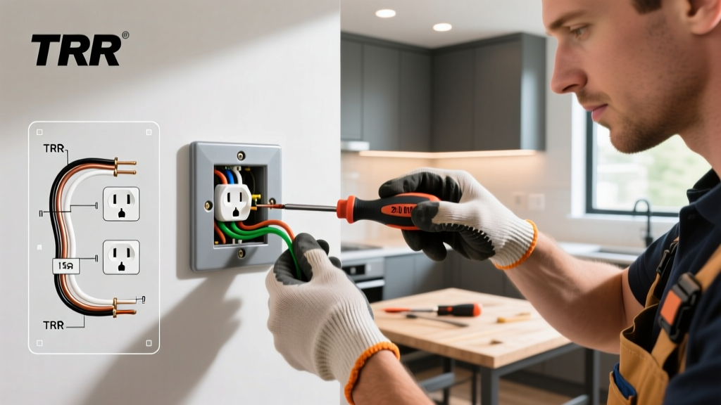
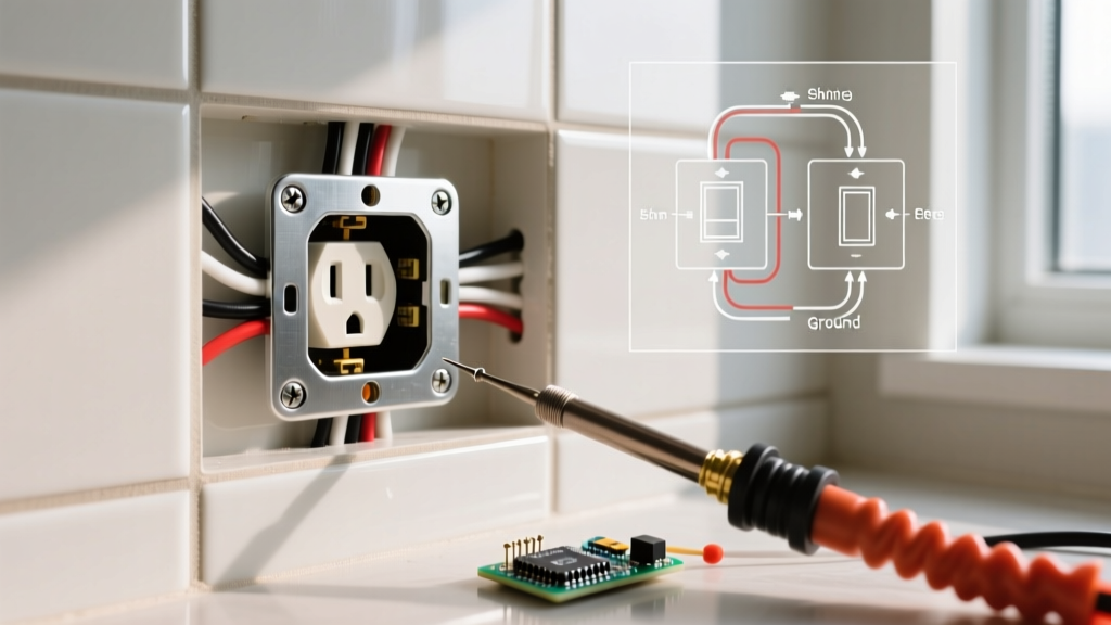
When upgrading a kitchen backsplash, installing bathroom tile, or adding wood paneling, the finished wall surface frequently extends past the edge of the existing electrical box. This results in a recessed receptacle—a sunken device that causes cover plates to crack, creates a fire hazard by exposing the interior of the wall cavity, and leaves the outlet wobbling when you plug in an appliance. The standard DIY fix is to use an electrical outlet shim. However, from a wiring diagram and spatial routing perspective, shimming a device is not just about stacking plastic washers; it fundamentally alters the physical geometry of your conductor routing.
In this comprehensive reference guide, we explore how to properly integrate an electrical outlet shim into your installation, ensuring compliance with the National Electrical Code (NEC) while maintaining the integrity of your physical wiring diagram.
Physical Wiring Diagrams: How Shims Alter Conductor Routing
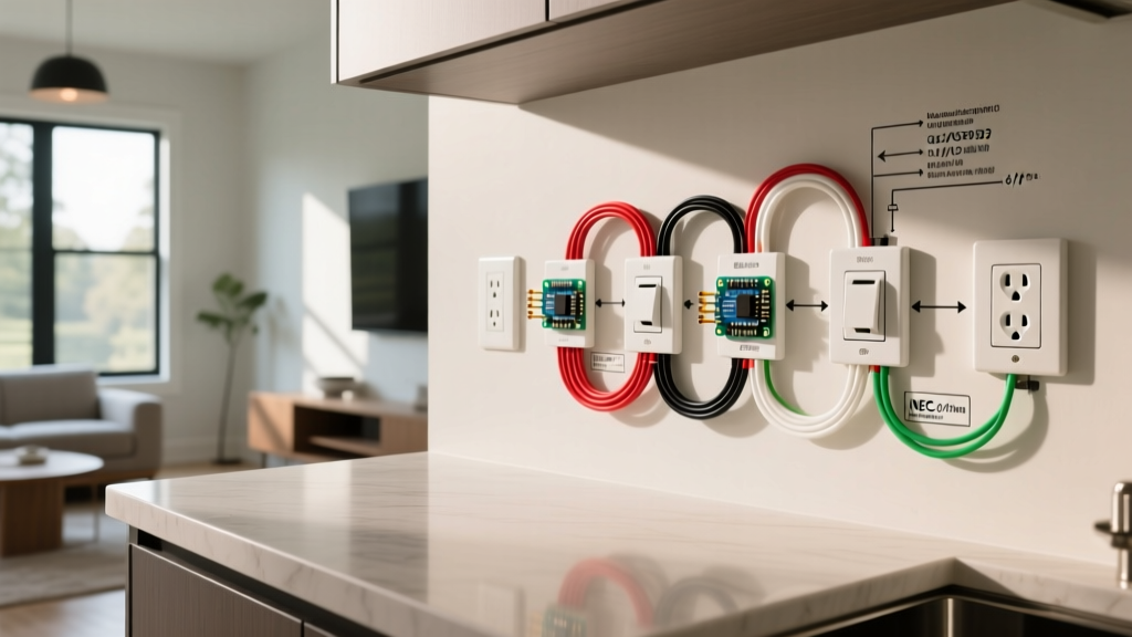
A standard schematic wiring diagram shows logical connections: line, load, neutral, and ground. But the physical wiring diagram—the actual spatial folding of 12 AWG or 14 AWG solid copper wire inside a single-gang box—is highly sensitive to depth. According to NFPA 70 (National Electrical Code) Article 300.14, you must maintain at least 6 inches of free conductor slack.
When you introduce a 3/8-inch stack of shims to bring a receptacle flush with a tiled wall, you consume a portion of that critical slack. If the original wiring was tightly folded, pushing the device yoke forward can place immense mechanical stress on the terminal screws or wire nuts, potentially leading to a high-resistance connection or a pulled neutral.
Expert Insight: Never simply pull the receptacle forward to meet the shim stack. You must physically unfold the conductors, reassess the accordion bends, and ensure the ground pigtail has enough length to reach the green grounding screw without stretching.
Box Depth, Tile Thickness, and Shim Sizing Matrix
Choosing the right shim thickness requires measuring the gap between the plaster ring (or box edge) and the finished surface. Below is a reference matrix to help you determine the correct shim configuration based on common remodeling scenarios.
| Finished Surface Material | Average Added Thickness | Gap Size | Recommended Shim / Extender Type |
|---|---|---|---|
| Standard Ceramic Tile | 1/4" to 3/8" | < 1/8" to 1/4" | Plastic U-Shaped Shims (e.g., Gardner Bender GS-8) |
| Natural Stone / Slate | 1/2" to 3/4" | > 1/4" | Metal Box Extender (e.g., C.R. Laurence RBE1) |
| Wood Beadboard / Paneling | 1/4" | < 1/8" | Plastic O-Ring Shims or Cardboard Spacers |
| Backerboard + Thinset + Tile | 5/8"+ | > 1/2" | Deep Metal Extender Ring + Outlet Shim Washers |
Code Compliance: The 1/8-Inch Rule and Material Selection
A common and dangerous mistake is stacking dozens of plastic U-shaped shims to bridge a massive 1/2-inch gap. This violates NEC Article 314.20, which dictates that in walls constructed of combustible materials (like drywall and wood studs), the box or an approved extension must be flush with the surface. More importantly, if the gap between the box and the receptacle yoke exceeds 1/8 inch, you must use a non-combustible metal box extender or an approved plaster ring.
Plastic electrical outlet shims are strictly designed to fine-tune the final 1/16" to 1/8" seating of the device yoke against the wall surface to prevent wobbling. They are not structural bridges for deep cavities.
Comparing Shim Materials
- Plastic U-Shaped Shims (Nylon/PVC): Cost roughly $2.50 for a 10-pack. Best for micro-adjustments. They slide over the mounting screws without requiring you to disconnect the wiring.
- Metal Box Extenders (Galvanized Steel): Cost $4.00 to $7.00 each. These slide into the existing box and physically extend the fire-containment boundary to the finished wall. Required for gaps > 1/8".
- Horsehair / Fibrous Washers: An older, traditional method. Largely obsolete in 2026 due to moisture degradation in bathrooms and kitchens.
Step-by-Step Installation & Wiring Verification
Follow this precise workflow to install your electrical outlet shim while maintaining a safe and code-compliant physical wiring diagram.
Step 1: De-energize and Map the Circuit
Turn off the breaker and verify zero voltage using a non-contact voltage tester and a digital multimeter. According to the Electrical Safety Foundation International (ESFI), verifying the absence of voltage at both the line and load terminals is mandatory before touching any device yoke.
Step 2: Extract and Assess Conductor Slack
Remove the 6-32 mounting screws and gently pull the receptacle out. Measure the gap from the metal box edge to the tile surface. If the gap is 3/8", you will need a 1/4" metal extender plus a 1/8" stack of plastic outlet shims. Check your wire nuts; if the wires are pulled taut when the device is at the new shimmed depth, you must undo the wire nuts and add short pigtails to restore the NEC-mandated 6-inch slack.
Step 3: Install the Extender and Stack the Shims
Insert the metal extender into the box, ensuring its internal flanges grip the sides securely. Next, slide the plastic U-shaped electrical outlet shims over the mounting screws. The open end of the 'U' should face downward or sideways so gravity and the pressure of the cover plate keep them seated against the yoke.
Step 4: Seat the Device and Torque
Push the receptacle back into the box. The shims will compress slightly against the tile. Tighten the 6-32 mounting screws until the yoke is firm and does not rock. While the NEC 110.14(D) torque requirements apply primarily to wire terminations (like lug connections on breakers), ensuring the mounting screws are snug prevents the device from shifting, which the Occupational Safety and Health Administration (OSHA) notes can lead to ground wire detachment and shock hazards over time.
Edge Cases and Troubleshooting Failure Modes
Even with the correct electrical outlet shim, specific edge cases can cause installation failures. Watch out for these scenarios:
- The 'Cracked Tile' Scenario: If your tile installer did not cut the drywall hole cleanly, the tile edge may be unsupported. Tightening the receptacle screws against a thick shim stack can act as a lever, cracking the ceramic edge. Fix: Use a slightly thicker shim to bridge the gap without over-tightening the screws, or apply a bead of clear silicone caulk behind the cover plate to distribute pressure.
- Ground Faults from Metal Extenders: If you are using a metal box extender and the hot terminal screw is loose, it can arc against the metal extender. Always use electrical tape to wrap the sides of the receptacle yoke (a practice known as 'mummy wrapping') to insulate the terminal screws from the metal extender walls.
- Multi-Gang Alignment Issues: In a 3-gang or 4-gang box, shimming one outlet can throw off the visual alignment of the entire cover plate. You must shim all devices in a multi-gang box to the exact same depth, using a laser level or a straight edge across the yokes before final tightening.
Frequently Asked Questions
Can I use cardboard as an electrical outlet shim?
No. Cardboard is highly combustible and degrades when exposed to humidity or minor electrical arcing. Always use UL-listed nylon, PVC, or galvanized steel shims and extenders.
Do shims affect the grounding path?
Plastic shims are non-conductive and are placed between the metal yoke and the wall surface, so they do not interrupt the grounding path. The ground path travels through the green grounding screw, the copper wire, and the metal box (if applicable). However, if you rely on the metal yoke touching a metal box for a ground (via the mounting screws), ensure the screws are tightly seated, as thick shim stacks can sometimes reduce the metal-to-metal contact pressure.
What is the maximum number of plastic shims I can stack?
Most manufacturers recommend stacking no more than three 1/16-inch plastic shims (totaling 3/16"). If your gap requires more than this, you must transition to a metal box extender to maintain fire containment and structural rigidity.