
The Complete Wiring Diagram for Switch and Outlet Reference
Wiring a switch and an outlet in the same electrical box—or on the same circuit—is one of the most common residential electrical tasks. Whether you are adding a switched lamp receptacle in a living room, wiring a bathroom vanity, or configuring a half-hot kitchen island outlet, understanding the exact wiring diagram for switch and outlet configurations is critical for safety and code compliance. In 2026, adherence to the latest National Electrical Code (NEC) regarding box fill, AFCI protection, and torque specifications is strictly enforced by local inspectors.
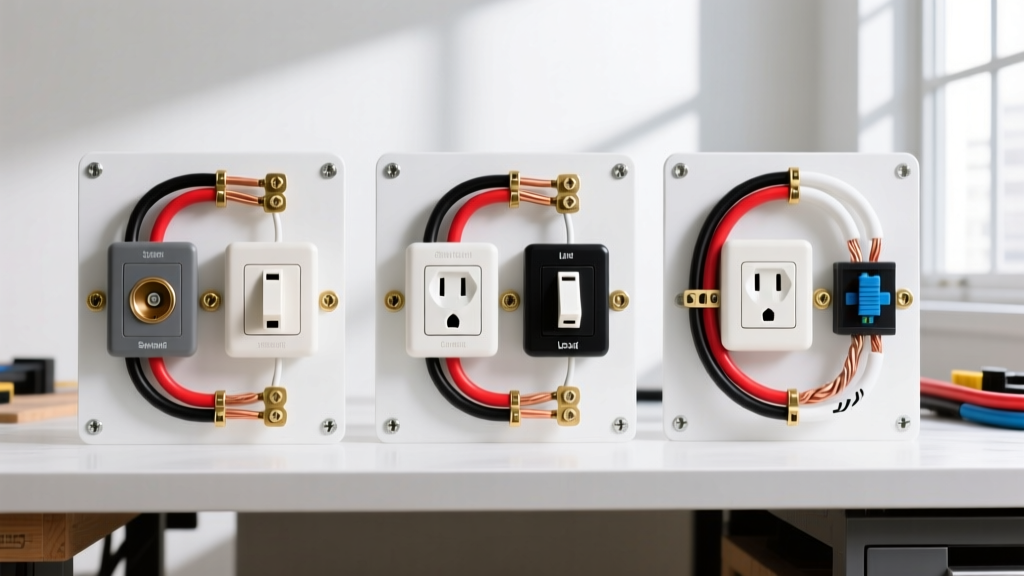
This reference guide breaks down the three primary configurations, complete with step-by-step wiring logic, box fill calculations, and professional-grade tool recommendations.
Essential Tools and Materials (2026 Pricing)
Before consulting the diagrams, ensure you have the correct materials. Professional electricians no longer rely on twist-on wire nuts for high-vibration or critical junctions; lever connectors are the modern standard.
- Receptacles: Leviton Decora 15A Tamper-Resistant (Model R52-05603-2WS) - ~$3.50 each.
- Switches: Leviton Single-Pole Toggle or Decora Rocker (15A/120V) - ~$2.00 each.
- Connectors: WAGO 221-413 (3-wire) and 221-412 (2-wire) Lever Nuts - ~$6.00 per 10-pack.
- Wire Strippers: Klein Tools 11055 (10-20 AWG) - ~$28.00.
- Torque Screwdriver: Milwaukee 48-22-9404 (Required by NEC 110.14(D) for terminals marked with torque values; Leviton specifies 14 in-lbs) - ~$115.00.
Core Concept: The Brass Fin Tab
The most misunderstood component in any wiring diagram for switch and outlet setups is the break-off fin tab. On a standard duplex receptacle, the two brass (hot) screws are connected by a small brass fin, and the two silver (neutral) screws are connected by a silver fin.
Expert Rule: You only break the brass (hot) tab when creating a split-wired (half-hot) outlet where one plug is always on and the other is controlled by a switch. Never break the silver neutral tab unless you are working with a highly specific Multi-Wire Branch Circuit (MWBC) requiring isolated neutrals, which is rare in modern single-box switch/outlet combos.
Configuration 1: The Switched Receptacle (Switch Controls Entire Outlet)
In this scenario, the wall switch acts as a master power control for the entire duplex outlet. This is commonly used in living rooms where a floor lamp is plugged in, and local code dictates that a switched lighting outlet must be present.
Wiring Logic & Steps
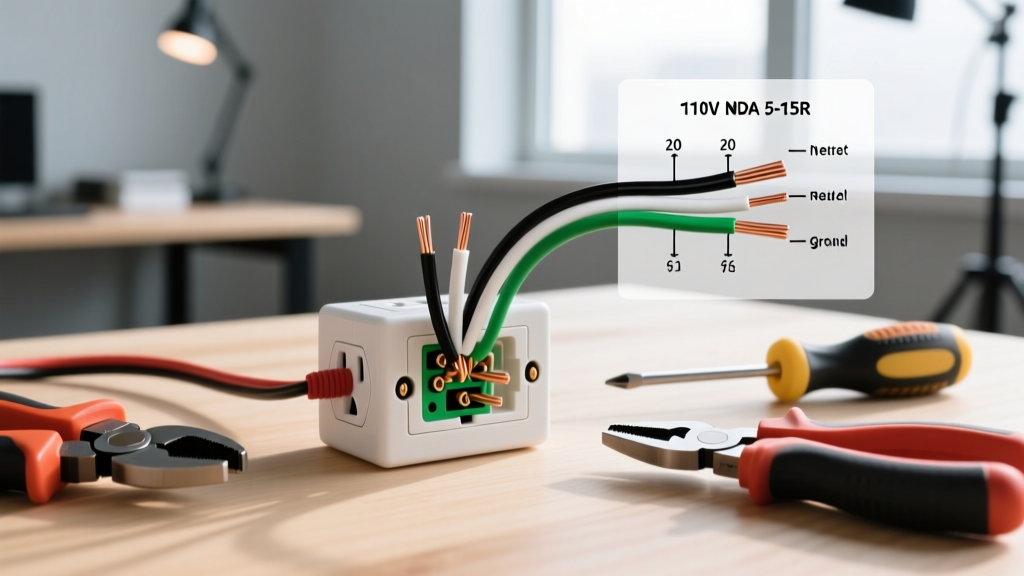
- Power Source to Switch: The incoming hot (black) wire from the breaker panel connects directly to the bottom brass terminal on the single-pole switch.
- Switch to Outlet (Switched Leg): A 2-wire cable runs from the switch box to the outlet box. The black wire in this cable connects to the top brass terminal on the switch. At the outlet, this black wire connects to the brass terminal.
- Neutral Continuity: All incoming white (neutral) wires are spliced together using a WAGO 221-413 lever nut and run continuously to the silver terminal on the outlet. The switch does not interact with the neutral.
- Grounding: All bare copper grounds are spliced together and pigtailed to both the green ground screw on the switch and the green ground screw on the outlet.
Configuration 2: Independent Switch and Always-Hot Outlet
Here, power enters the box and feeds both a switch (which controls a separate ceiling light) and an outlet (which remains always-hot). This is the standard bedroom or hallway configuration.
Wiring Logic & Steps
- Hot Pigtailing: The incoming black (hot) wire is spliced with two pigtails using a WAGO connector. One pigtail goes to the switch's brass terminal; the other goes to the outlet's brass terminal.
- Switched Leg to Light: The black wire leaving the switch's second terminal travels up to the ceiling fixture.
- Neutral Pigtailing: The incoming white wire is spliced with a pigtail to the outlet's silver terminal, while the main white wire continues to the ceiling light.
- Grounding: Pigtail all grounds to both devices and the metal box (if applicable).
Configuration 3: The Half-Switched / Half-Hot Split Receptacle
This configuration provides an always-hot top plug and a switch-controlled bottom plug. It requires either a 3-wire cable (14/3 or 12/3 NM-B) running from the switch to the outlet, or two separate 2-wire cables if power originates at the outlet box.
Wiring Logic & Steps (Power at Switch Box)
- At the Switch: Incoming hot (black) connects to the switch. A 3-wire cable runs to the outlet. The black wire of the 3-wire connects to the switch (always-hot feed). The red wire of the 3-wire connects to the switch's load terminal (switched feed).
- At the Outlet (The Critical Step): Use needle-nose pliers to snap off the brass fin tab separating the top and bottom brass screws. Leave the silver tab intact.
- Terminations: Connect the black wire (always-hot) to the top brass screw. Connect the red wire (switched-hot) to the bottom brass screw.
- Neutral & Ground: The white wire connects to the silver screw. Grounds are bonded as usual.
Comparison Matrix: Choosing Your Configuration
| Configuration | Primary Use Case | Fin Tab Broken? | Cable Required (Switch to Outlet) |
|---|---|---|---|
| Switched Receptacle | Lamp control in windowless rooms | No | 14/2 or 12/2 (2-wire) |
| Independent | Ceiling fan/light + device charging | No | N/A (Devices share same box) |
| Half-Hot Split | Living room lamps + always-on vacuum | Yes (Brass only) | 14/3 or 12/3 (3-wire) |
NEC Box Fill Calculations (Article 314.16)
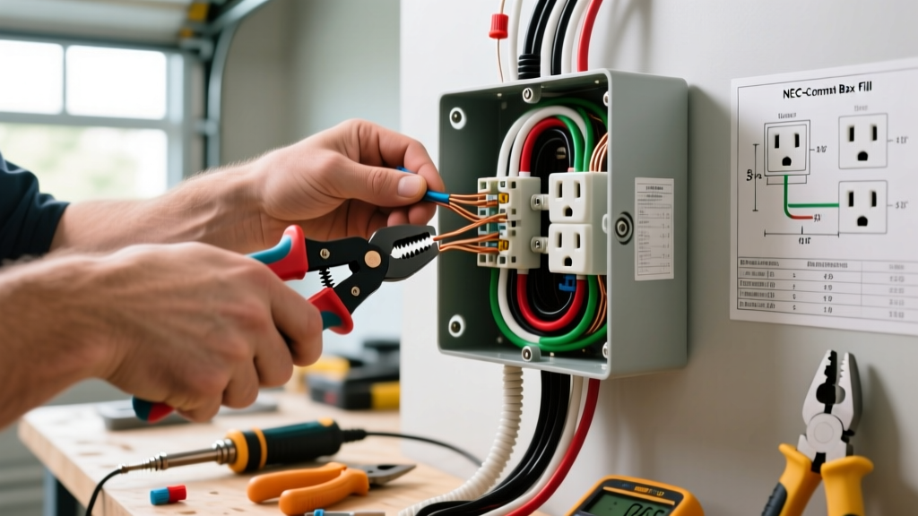
A common failure point in DIY wiring is overcrowding the electrical box. The NEC strictly limits the number of wires and devices in a single gang box to prevent overheating. According to the NFPA 70 (NEC), you must calculate cubic inch fill.
The Math for a Standard Independent Setup (14 AWG Wire)
For 14 AWG wire, each conductor counts as 2.0 cubic inches.
- Hot Wires: 1 incoming + 1 outgoing to light + 2 pigtails = 4 wires (8.0 cu in)
- Neutral Wires: 1 incoming + 1 outgoing + 1 pigtail = 3 wires (6.0 cu in)
- Grounds: All grounds count as a single 2.0 cu in allowance.
- Clamps: Internal cable clamps count as 2.0 cu in.
- Devices: Each switch or outlet counts as 2 wires (4.0 cu in per device x 2 = 8.0 cu in).
- Total Required: 26.0 cubic inches.
Expert Tip: A standard single-gang 'old work' box is only 14 to 18 cubic inches. For a switch and outlet in the same location, you must use a double-gang box (typically 30+ cubic inches) and a 2-gang Decora wall plate.
AFCI and GFCI Code Compliance
Modern electrical codes heavily mandate arc-fault and ground-fault protection. The Consumer Product Safety Commission (CPSC) notes that GFCIs prevent over 300,000 residential shocks annually.
- GFCI (Wet Locations): If this switch/outlet combo is in a bathroom, kitchen, or garage, the outlet must be GFCI protected. You can use a GFCI receptacle for the outlet and a standard switch for the light. Wire the incoming power to the LINE terminals of the GFCI. Do not wire the switch to the LOAD terminals unless you specifically want the switch to have GFCI protection (which is unnecessary and can cause nuisance tripping).
- AFCI (Living Spaces): For bedrooms and living rooms, AFCI protection is required. This is best handled at the circuit breaker panel rather than using an AFCI receptacle in a cramped double-gang box.
Troubleshooting Common Wiring Failures
Problem: The 'Switched' Outlet is Always Hot
Cause: You failed to break the brass fin tab on the receptacle. Even if you wired the red and black wires to separate screws, the intact brass tab bridges the connection, feeding constant power to both halves. Fix: Turn off the breaker, pull the outlet out, and use side-cutters to snap the brass tab cleanly in half.
Problem: The Switch Works, but the Outlet Trips the Breaker
Cause: A ground fault or a short circuit. Often, the bare copper ground wire is touching the brass terminal screw because the wire was stripped too far back (more than 3/4 inch). Fix: Trim the copper back, re-strip to exactly 5/8 inch, and ensure no bare copper is visible outside the terminal saddle.
Final Safety Directives
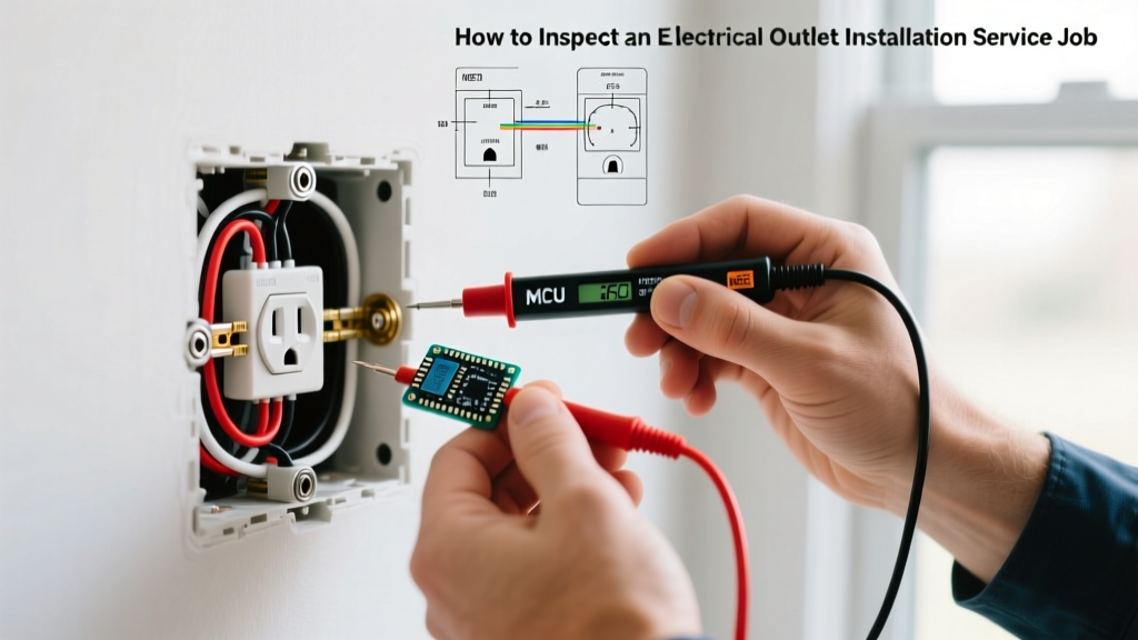
Always verify power is off using a non-contact voltage tester and a multimeter before touching any terminals. For comprehensive workplace and residential electrical safety standards, refer to the OSHA Electrical Safety guidelines. When tightening terminal screws, use a calibrated torque screwdriver set to the manufacturer's specification (usually 14 in-lbs for 15A Leviton devices) to prevent loose connections that cause arc faults over time.