
Understanding the Legacy NEMA 10-30R Configuration
When working with heavy 240-volt appliances in older homes, mastering the wiring diagram for 3 prong dryer outlet configurations is a critical safety skill. The NEMA 10-30R receptacle was the standard for electric dryers for decades. Unlike modern 4-prong setups that separate the neutral and ground wires, the 3-prong system relies on a single combined neutral-ground conductor.
While the National Electrical Code (NEC) mandated 4-prong outlets (NEMA 14-30R) for all new construction starting in 1996, millions of older homes still feature existing, grandfathered 3-prong circuits. According to the National Fire Protection Association (NFPA), replacing a damaged legacy receptacle or wiring a new 3-prong cord to a dryer in an unmodified older home is permissible under NEC Article 250.140, Exception 1. However, the margin for error is zero. A miswired 3-prong outlet can energize the dryer's metal chassis, creating a lethal shock hazard.
Safety Warning: You may only install or replace a 3-prong NEMA 10-30R outlet on an existing branch circuit. If you are running a new circuit from the panel in 2026, you are legally required to install a 4-prong NEMA 14-30R outlet with a dedicated equipment grounding conductor.
Anatomy of the 3-Prong Dryer Wiring Diagram
A standard 3-prong dryer circuit utilizes 10/3 NM-B (Romex) or 10/3 SER cable, which contains two hot wires and one neutral wire. There is no dedicated bare copper ground wire in this legacy cable. The neutral wire serves a dual purpose: it carries the unbalanced 120V return current for the dryer's motor and timer, and it bonds to the chassis for fault protection.
| Terminal Marking | Wire Color (10/3 Cable) | Function | Voltage Potential |
|---|---|---|---|
| X (Left Brass) | Black | Hot Leg 1 | 120V to Neutral / 240V to Y |
| Y (Right Brass) | Red | Hot Leg 2 | 120V to Neutral / 240V to X |
| W (Center Silver) | White (or Bare in older SE) | Neutral / Ground Bond | 0V (Carries unbalanced return) |
Tools and Materials Required
Do not attempt this installation with generic household tools. 30-amp 240V circuits require precision torque and heavy-duty components to prevent arcing and thermal failure.
- Receptacle: Leviton 51030 or Hubbell HBL2610 (30A, 125/250V, NEMA 10-30R)
- Cable: 10/3 NM-B with ground (Note: The bare ground in modern 10/3 is capped off and unused in a 3-prong setup, or you must use legacy 10/2 with ground where the white is re-identified, though 10/3 is standard).
- Multimeter: Fluke 117 or Klein Tools MM400 (CAT III 600V minimum)
- Torque Screwdriver: Klein Tools 69000 or CDI 1002MFRMH (Must measure in inch-pounds)
- Wire Strippers: Klein Tools 11055 (Capable of stripping #10 AWG)
- Cable Clamp: 3/4-inch metallic or heavy-duty plastic NM cable connector
Step-by-Step Installation Guide
Step 1: Lockout, Tagout, and Verify
Navigate to your main service panel and switch off the 30-amp double-pole breaker supplying the dryer circuit. Apply a padlock or tape to prevent accidental re-engagement. At the outlet location, remove the cover plate and use your Fluke 117 multimeter to test across the two hot slots, and from each hot slot to the center neutral slot. The reading must be exactly 0.00V. The Electrical Safety Foundation International (ESFI) emphasizes that assuming a circuit is dead without testing is a leading cause of residential electrocution.
Step 2: Prepare the 10/3 Cable
Strip back the outer PVC jacket of the 10/3 NM-B cable exactly 8 inches from the entry point of the electrical box. Strip exactly 3/4 inch of insulation from the black, red, and white wires. Do not strip more than 3/4 inch; exposed copper outside the terminal block creates a short-circuit risk. If your modern 10/3 cable includes a bare copper ground wire, cap it with a yellow wire nut and tuck it into the back of the box—it is not used in a NEMA 10-30R configuration.
Step 3: Terminate the Receptacle
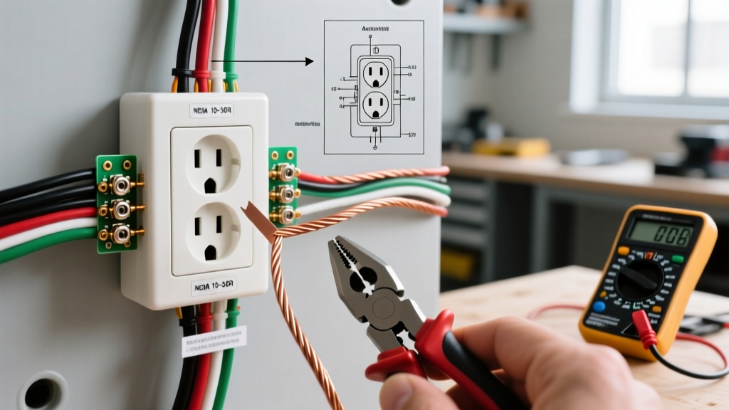
Follow the wiring diagram for 3 prong dryer outlet terminals strictly:
- Insert the Black wire into the left brass terminal (X).
- Insert the Red wire into the right brass terminal (Y).
- Insert the White wire into the center silver terminal (W).
Because the white wire acts as the neutral-ground bond, it must be securely fastened. A loose neutral on a 240V circuit is a severe fire hazard, as it forces the dryer's 120V components to seek a ground path through the user or the appliance chassis.
Step 4: Apply Precision Torque
Hand-tighten the terminal screws, then use your calibrated torque screwdriver set to 18 inch-pounds (verify the specific manufacturer's spec sheet, typically between 14-18 in-lbs for 30A Leviton/Hubbell devices). The U.S. Consumer Product Safety Commission (CPSC) notes that thermal expansion and contraction from high-draw appliances like dryers will gradually loosen hand-tightened screws, leading to resistance heating and melted receptacles.
Step 5: Secure the Cable and Receptacle
Feed the wires neatly into the single-gang deep box. Secure the NM cable using a 3/4-inch cable clamp at the knockout to ensure no strain is transferred to the terminal screws. Push the receptacle into the box, ensuring the ground strap (if present on the yoke) makes contact with the metal box. Secure with the provided 6-32 machine screws and install the heavy-duty phenolic cover plate.
The Dryer Side: The Critical Bonding Strap
Wiring the wall outlet is only half the equation. The wiring diagram for a 3 prong dryer outlet is incomplete without addressing the dryer's terminal block. Modern dryers ship with a 4-prong cord and the neutral-ground bond removed. If you are plugging into a legacy 3-prong wall outlet, you must install a 3-prong dryer cord (NEMA 10-30P) and reinstall the bonding strap.
How to Configure the Dryer Terminal Block for 3-Prong
- Remove the dryer's rear access panel to expose the terminal block.
- Connect the center wire (White/Neutral) of the 3-prong cord to the center silver terminal on the dryer.
- Connect the two outer wires (Black and Red) to the outer brass terminals. Polarity does not matter here.
- The Bonding Step: Locate the green bonding strap or a #10 AWG green grounding wire provided with the dryer. Connect one end to the center silver terminal (along with the white cord wire) and the other end to the dryer's metal chassis ground screw.
Failure to install this bonding strap means the dryer's metal drum and exterior will have no path to trip the breaker in the event of an internal short circuit.
Comparison: 3-Prong vs. 4-Prong Dryer Setups
If you are renovating or have the option to upgrade, understanding the differences between these two systems will help you make a safe, code-compliant decision.
| Feature | 3-Prong (Legacy NEMA 10-30) | 4-Prong (Modern NEMA 14-30) |
|---|---|---|
| Wires Required | 3 (Hot, Hot, Neutral/Ground) | 4 (Hot, Hot, Neutral, Ground) |
| Safety Ground | Combined with Neutral | Dedicated Equipment Ground |
| Dryer Bonding Strap | Required (Neutral to Chassis) | Removed (Isolated Neutral) |
| NEC Compliance (New) | Prohibited for new installs | Mandated for all new installs |
| Shock Risk Profile | Higher (if neutral fails) | Lowest (redundant safety) |
Frequently Asked Questions
Can I use an adapter to plug a 4-prong dryer into a 3-prong outlet?
No. The NEC strictly prohibits the use of plug adapters (often called 'cheater cords') to convert a 4-prong plug to a 3-prong receptacle. You must physically change the power cord on the dryer to a NEMA 10-30P and configure the internal bonding strap. Adapters lack the mechanical stability for 30-amp loads and bypass critical safety bonding.
My 10/3 cable has a bare ground and a white neutral. Which one goes to the 'W' terminal?
In a 3-prong NEMA 10-30R setup, the white insulated neutral wire must be connected to the 'W' (center) terminal. The bare copper ground wire is capped off with a wire nut and left unused in the box. The white wire is sized to carry the unbalanced 120V return current, whereas the bare ground is not designed for continuous current flow.
Why does my 3-prong dryer outlet feel warm to the touch?
A warm outlet indicates high electrical resistance, almost always caused by loose terminal screws or oxidized wire connections. Immediately shut off the breaker. Remove the receptacle and check for melted plastic or scorched wires. If the terminals show heat damage, the receptacle must be replaced, and the wire ends must be cut back to expose clean copper before re-terminating with a torque screwdriver.