
The Evolution of the Single-Pole Switch in 2026
Upgrading your home’s lighting controls is one of the most cost-effective ways to modernize your electrical system, improve energy efficiency, and integrate smart home ecosystems. While the standard 15-amp toggle switch has been a staple in residential construction for decades, the shift toward smart switches, advanced dimmers, and USB-integrated receptacles has fundamentally changed how we approach lighting upgrades. Whether you are replacing a cracked, yellowed toggle with a sleek Leviton Decora rocker or installing a Wi-Fi-enabled smart switch, understanding the underlying electrical topology is non-negotiable.
According to the U.S. Consumer Product Safety Commission (CPSC), improper electrical wiring and loose terminal connections are leading causes of residential arc faults and electrical fires. This guide provides a comprehensive, electrician-grade approach to upgrading your single-pole switches, complete with torque specifications, edge-case troubleshooting, and a clear mental model of the circuit.
Decoding the Wiring Diagram for Single Light Switch Circuits
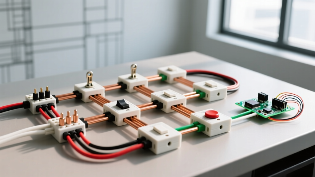
Before touching a screwdriver, you must visualize the current path. A single-pole switch controls a light fixture from one location. The fundamental wiring diagram for single light switch setups involves interrupting the "hot" (ungrounded) conductor while allowing the neutral (grounded) conductor to pass through to the fixture.
Standard Cable Anatomy and NEC Color Codes
In a typical 2026 residential setup using 14/2 or 12/2 NM-B (Romex) cable, you will encounter four distinct conductors in the switch box:
- Line (Hot): The black wire bringing 120V power from the breaker panel to the switch.
- Load: The black wire carrying power from the switch to the light fixture. (Note: In a switch loop, the white wire may be used as the Line or Load and must be re-identified with black tape per NEC Article 200.7).
- Neutral: The white wire. Historically, standard mechanical switches did not connect to the neutral wire. However, modern smart switches and LED-compatible dimmers require a neutral connection to power their internal Wi-Fi radios or microprocessors.
- Ground: The bare copper or green wire, essential for fault current clearing and shock prevention.
Pro-Tip for Older Homes: If your home was built before 1985, you likely have a "switch loop" where the white wire in the 2-wire cable dropping to the switch is actually acting as the hot Line wire. Always verify with a non-contact voltage tester and a multimeter before assuming wire functions based on color.
Upgrade Matrix: Standard vs. Dimmer vs. Smart Switches
Choosing the right replacement switch dictates your wiring requirements. Below is a comparison of the most common 2026 upgrade paths for single-pole applications.
| Switch Type | Example Model (2026) | Avg. Cost | Neutral Required? | Best Use Case |
|---|---|---|---|---|
| Standard Rocker | Leviton Decora 5603 | $3 - $6 | No | Basic aesthetic upgrades, high-reliability mechanical switching. |
| LED Dimmer | Lutron Diva DVCL-153P | $25 - $35 | No | Dining rooms, bedrooms. Requires adjusting low-end trim to prevent LED flicker. |
| Wi-Fi Smart Switch | Kasa Smart KS220M | $20 - $30 | Yes (Strict) | Routine scheduling, voice control. Fails without a neutral wire. |
| Proprietary RF Smart | Lutron Caseta PD-5S-DV | $55 - $70 | No | Older homes lacking neutral wires. Uses a wireless Pico remote for 3-way conversion. |
Step-by-Step Replacement Protocol
Follow this precise sequence to ensure a safe, code-compliant installation. You will need a Klein Tools 11055 wire stripper, a Fluke 1AC-II VoltAlert, and a Wiha insulated torque screwdriver.
- De-energize and Verify: Turn off the circuit breaker. Do not rely solely on the switch position. Place the Fluke 1AC-II against the switch plate and wires. Verify zero voltage.
- Extract the Old Device: Remove the faceplate and mounting screws. Pull the switch out gently. Take a photo of the existing wiring before disconnecting anything.
- Inspect the Conductors: Check for brittle insulation, scorch marks, or copper oxidation. If the wire is damaged, strip back 3/4 inch of insulation to expose fresh copper.
- Identify Line and Load: If the old wiring is ambiguous, use a multimeter to identify the constant hot (Line) and the switched hot (Load) once power is temporarily restored, then kill the power again.
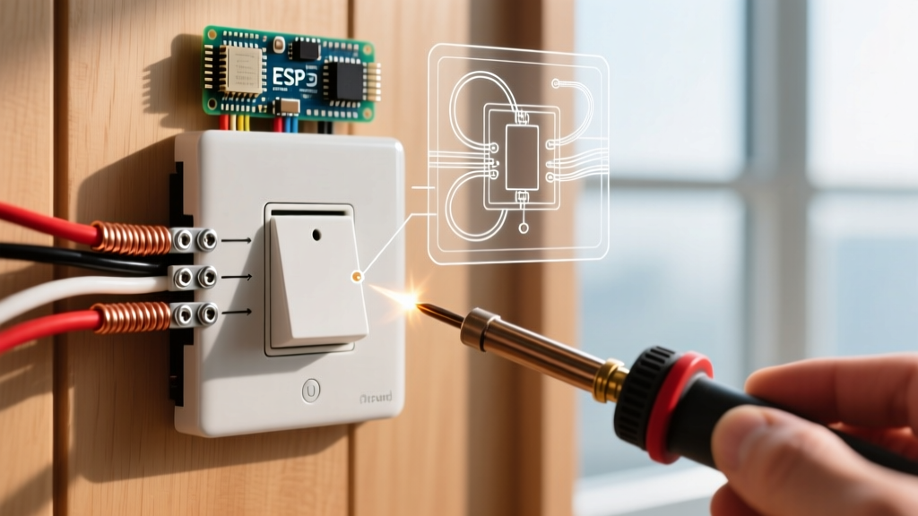
- Make the Connections: For standard switches, connect the Line to the bottom brass terminal and the Load to the top brass terminal. Connect the bare ground to the green ground screw. If installing a smart switch, connect the white neutral pigtail to the bundle of white wires in the back of the box using a Wago 221 lever nut.
- Torque the Terminals: This is where DIYers fail. Loose connections cause arcing. Use a torque screwdriver set to 12 to 14 inch-pounds (or the manufacturer’s specific rating printed on the device) to secure the terminal screws.
- Box Dressing and Mounting: Carefully fold the wires in an accordion pattern to avoid pinching. Mount the switch using the provided 6-32 machine screws, ensuring the strap sits flush against the drywall or plaster ring.
Critical Edge Cases & Troubleshooting
Real-world electrical boxes rarely match textbook diagrams perfectly. Here is how to handle the most common upgrade roadblocks.
The "No Neutral" Dilemma
You bought a Wi-Fi smart switch, opened the box, and found only two black wires and a ground. This is a classic switch loop lacking a neutral conductor. Do not bootleg a ground as a neutral. This creates a severe shock hazard and will trip AFCI/GFCI breakers. Solution: Return the Wi-Fi switch and purchase a no-neutral smart switch like the Lutron Caseta series, or install a smart bulb in the fixture and use a standard mechanical switch to keep the circuit constantly powered.
The Danger of "Backstabbing"
Many cheap builder-grade switches feature push-in "backstab" connectors on the rear. While UL-listed, these spring-loaded connections are notorious for losing tension over time, leading to high resistance, heat buildup, and eventual failure. When upgrading, always use the side-terminal screws or the screw-to-clamp plates found on premium 2026 devices. Wrap the wire clockwise around the screw so tightening the screw pulls the loop closed.
Dealing with Aluminum Branch Wiring
If your home was built between 1965 and 1973, you may encounter aluminum branch wiring (marked AL or ALUM on the jacket). Standard copper-rated switches will react galvanically with aluminum, causing oxidation and fire. You must use switches specifically marked CO/ALR (Copper-Aluminum Revised), or pigtail the aluminum wire to copper using an AlumiConn lug connector before attaching it to a standard switch.
Code Compliance and Safety Standards
As smart home technology proliferates, the National Fire Protection Association (NFPA) and the National Electrical Code (NEC) continually update requirements for box fill capacity and thermal management. Smart switches are physically deeper than standard toggles, often requiring a minimum of 18 cubic inches of box volume. If your existing electrical box is overcrowded, you may need to install a box extender or replace the box entirely to meet NEC Article 314 fill calculations.
Furthermore, the U.S. Department of Energy highlights that upgrading to automated lighting controls and high-efficacy LED dimmers can reduce residential lighting energy consumption by up to 30%. By combining a proper understanding of your wiring diagram with modern, high-quality components, you ensure both the safety of your household and the longevity of your electrical infrastructure.