
The Reality of "Wireless" Electrical Outlets in Modern Wiring
When homeowners and DIYers search for a wireless electrical outlet, they are often met with conflicting information. True wireless power transfer (WPT) capable of safely delivering 1800W (15A at 120V) through the air does not exist for residential applications due to severe thermal, efficiency, and safety limitations. Instead, in the context of residential electrical wiring, a "wireless electrical outlet" refers to a hardwired 120V NEMA 5-15R or 5-20R receptacle that integrates wireless control logic—either via Wi-Fi, Zigbee, or RF protocols—allowing you to switch the outlet's power state remotely without running new low-voltage control wires.
As of 2026, there are two primary methods to achieve this: installing a direct-wire Wi-Fi smart receptacle (like the Leviton Decora Smart Wi-Fi Outlet) or hiding a micro-relay module (like the Shelly Plus 1PM) behind a standard duplex receptacle. This wiring diagram reference will break down both methods, complete with National Electrical Code (NEC) compliance checks, box fill calculations, and step-by-step wiring sequences.
NEC Code & Box Fill Calculations: The Hidden Hurdle
Before pulling any wires, you must address NEC Article 314.16 regarding box fill calculations. Smart outlets and hidden relay modules take up significantly more physical volume inside a junction box than standard "dumb" receptacles.
- Standard Single-Gang Box: Typically offers 18 cubic inches of space.
- Standard Duplex Receptacle: Counts as 4 cubic inches (2 cu in per yoke/strap for 14 AWG wire).
- Smart Receptacle (e.g., Leviton DW15R): The internal electronics require a deeper yoke, effectively consuming up to 6 cubic inches of usable space.
- Hidden Micro-Relay (e.g., Shelly Plus 1PM): The module itself takes up roughly 3.5 cubic inches, plus the wire connectors required to splice it.
Expert Recommendation: If you are retrofitting a wireless outlet, upgrade your existing shallow metal or plastic box to a deep 22.5 cubic inch single-gang box, such as the Carlon B618R (approx. $4.50). This prevents wire crimping, which can lead to arcing, overheating, and catastrophic failure over time.
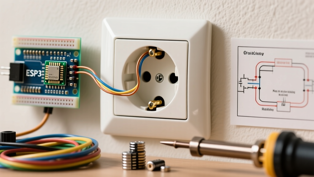
Wiring Diagram 1: Direct-Wire Wi-Fi Smart Receptacle
The most straightforward approach is replacing your existing receptacle with a dedicated smart outlet. The Leviton Decora Smart Wi-Fi Outlet (Model DW15R-2RW) is an industry standard, retailing for approximately $42. It requires a 2.4GHz Wi-Fi network and, crucially, a neutral wire.
Tools & Materials Required
- Leviton DW15R-2RW Smart Outlet
- Klein Tools 11063 wire strippers (for clean 14 AWG / 12 AWG cuts)
- Wago 221 lever nuts (for secure, space-saving pigtails)
- Non-contact voltage tester and digital multimeter
Step-by-Step Wiring Sequence
- Power Off & Verify: Turn off the 15A or 20A breaker at the main panel. Verify zero voltage at the receptacle using a multimeter (Line to Neutral, Line to Ground).
- Identify Wires: Locate the Line (hot, usually black), Load (downstream hot, if applicable), Neutral (white bundle), and Ground (bare copper or green).
- Connect the Ground: Attach the bare copper ground wire to the green grounding screw on the Leviton outlet. Torque to manufacturer specs (usually 12-14 in-lbs).
- Connect the Neutral: The DW15R has a dedicated silver terminal marked "WHITE/NEUTRAL". Connect your neutral bundle here. Note: Do not put the neutral on the brass load terminal.
- Connect Line and Load: Attach the incoming hot (Line) wire to the brass terminal marked "LINE". If this outlet feeds downstream devices, attach the outgoing hot wire to the brass terminal marked "LOAD".
- Boot & Pair: Restore power at the breaker. The LED on the outlet will flash amber. Use the My Leviton app to connect the device to your 2.4GHz Wi-Fi network.
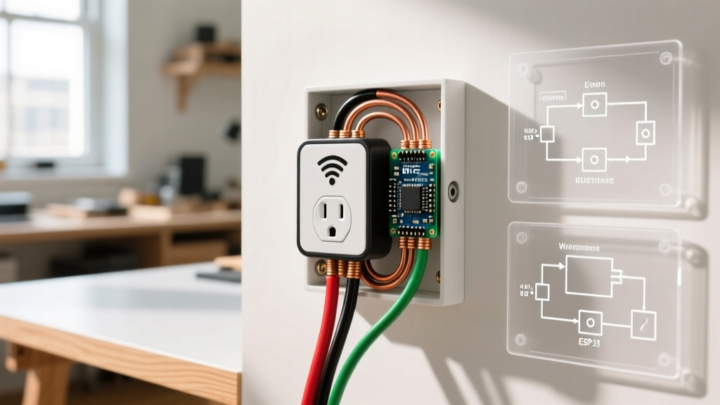
Wiring Diagram 2: Hidden Micro-Relay Behind a Standard Duplex
If you want to maintain the aesthetic of standard, low-profile receptacles (or need to use specialized tamper-resistant hospital-grade outlets), you can wire a wireless micro-relay behind the scenes. The Shelly Plus 1PM (Model SNSW-001P16US) is a 16A Wi-Fi relay with built-in power metering, costing around $18.
Safety Warning: According to OSHA electrical safety guidelines, all splices inside a junction box must be securely fastened and the box must remain accessible. Never bury a relay module inside a closed wall cavity without a junction box cover.
The Pigtail Wiring Method
Because the Shelly relay must intercept the hot wire while passing the neutral to both itself and the receptacle, we use a pigtail configuration.
- Neutral Splice: Connect the incoming neutral wire, a 6-inch white pigtail, and the Shelly "N" terminal wire together using a Wago 221 3-port lever nut.
- Receptacle Neutral: Connect the other end of the white pigtail to the silver terminal on the standard duplex receptacle.
- Line In: Connect the incoming hot (black) wire directly to the Shelly "L" terminal using a lever nut.
- Switched Output: Connect a 6-inch black pigtail from the Shelly "SW" (Switched Output) terminal to the brass "LINE" terminal on the duplex receptacle.
- Ground Bypass: The Shelly Plus 1PM does not require a ground for its internal logic, but the receptacle does. Pigtail the bare copper ground wires directly to the receptacle's green screw.
- Configuration: Power the circuit. Access the Shelly's local web interface (192.168.33.1) via your phone to configure it to your home Wi-Fi and set the relay to "Normally Open".
Technology Comparison Matrix
Choosing the right wireless outlet solution depends on your budget, box space, and smart home ecosystem. Below is a 2026 comparison of the most viable methods.
| Feature | Leviton DW15R (Smart Receptacle) | Shelly Plus 1PM (Hidden Relay) | Standard Wi-Fi Smart Plug (Dongle) |
|---|---|---|---|
| Average Cost | $42.00 | $18.00 (plus $2 for standard outlet) | $12.00 - $25.00 |
| Max Continuous Load | 15 Amps (1800W) | 16 Amps (1920W) | 15 Amps (1800W) |
| Box Space Required | Deep Box (22.5 cu in) | Deep Box (22.5 cu in) | N/A (Plugs into existing) |
| Neutral Wire Required? | Yes (Strict) | Yes (Strict) | Yes (Inherent to plug) |
| Power Metering | No | Yes (Real-time Wattage) | Varies by brand |
| Aesthetics | Clean, Decora paddle style | Invisible (Standard duplex) | Bulky, blocks adjacent plugs |
Edge Cases & Advanced Troubleshooting
Even with perfect wiring diagrams, wireless electrical outlets present unique edge cases that standard receptacles do not. Below are the most common failure modes encountered in the field.
1. The Faraday Cage Effect (Wi-Fi Dropping)
If you install a Wi-Fi smart outlet or hidden relay inside a metal steel gang box, the metal acts as a Faraday cage, severely attenuating the 2.4GHz Wi-Fi signal. This results in the outlet frequently showing as "Offline" in your smart home app.
Solution: Swap the metal box for a PVC/fiberglass deep box (like the Carlon B618R). If structural requirements mandate a metal box, use a relay with an external antenna pigtail and route the antenna outside the drywall, or switch to a Zigbee/Z-Wave relay which operates on lower frequencies that penetrate metal slightly better.
2. Multi-Wire Branch Circuits (MWBC) and Shared Neutrals
In older homes, you may encounter an MWBC where two hot wires (on opposing phases) share a single neutral wire. Never install a wireless smart outlet on an MWBC without separating the neutrals. Smart outlets monitor the current return on the neutral wire to detect faults and manage internal power supplies. A shared neutral will cause the smart outlet's internal logic board to read erroneous current data, leading to phantom tripping, inaccurate power metering, or catastrophic failure of the outlet's internal shunt.
Solution: Run a new dedicated 12/2 or 14/2 Romex line from the panel, or install a 2-pole handle tie and separate the neutral bundles at the nearest accessible junction box upstream.
3. Ghost Switching and Induced Voltage
When running long parallel cable lengths (over 50 feet) to a wireless outlet, the capacitance between the wires can induce a "ghost voltage" (often 10V-30V) on the switched load wire. This can cause LED lamps plugged into the wireless outlet to flicker or glow dimly even when the relay is in the "OFF" state.
Solution: Install a bypass capacitor (such as the Shelly Bypass or a 0.1µF X2 rated capacitor) directly across the Line and Load terminals at the receptacle. This absorbs the induced capacitive coupling and ensures a hard "OFF" state.
Final Safety and Commissioning Checklist
Before closing up the wall plate and commissioning your wireless electrical outlet, verify the following:
- All wire connections are pulled with 2 lbs of force to ensure they are seated in the Wago lever nuts or terminal screws.
- The ground loop is continuous and measures less than 0.5 ohms to the main panel ground bus.
- A GFCI tester (if applicable downstream) confirms correct wiring polarity.
- The smart device firmware is updated to the latest 2026 security patch to prevent local network vulnerabilities.
For more information on optimizing home energy usage with smart devices, refer to the U.S. Department of Energy's guide on smart plugs and switches. By following these precise wiring diagrams and respecting box fill limitations, your wireless outlet setup will provide reliable, code-compliant service for years to come.