
Introduction to the 50-Amp RV Receptacle (NEMA 14-50R)
As recreational vehicles have evolved into fully electrified, luxury homes on wheels, their power demands have surged. Modern 50-amp RVs routinely operate dual roof-mounted air conditioners, residential refrigerators, induction cooktops, and onboard washer/dryer combos simultaneously. To support this, the NEMA 14-50R receptacle has become the undisputed standard for high-capacity RV power pedestals and residential driveway hookups.
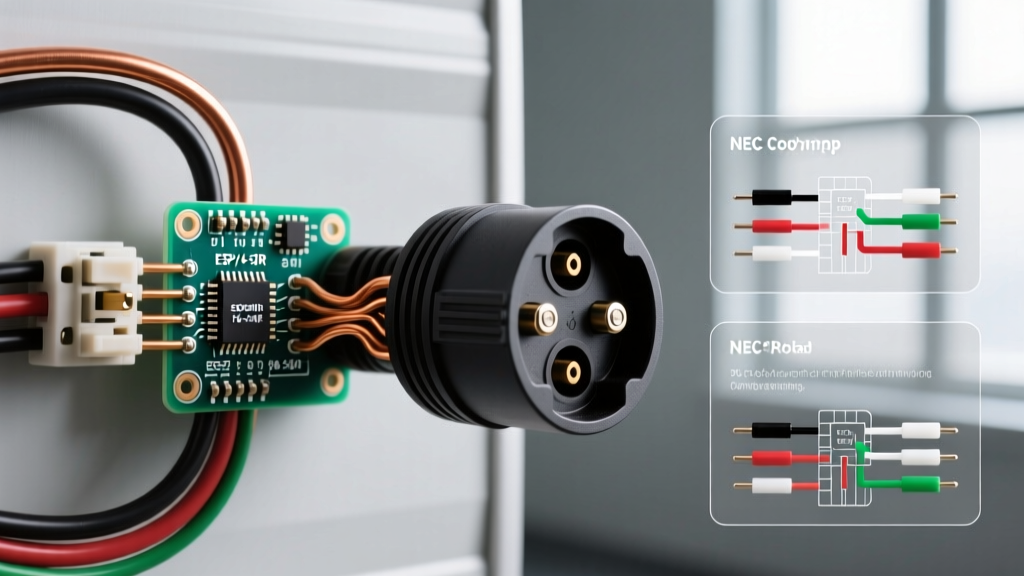
However, installing a 50-amp outlet is not as simple as swapping a standard 15-amp duplex receptacle. The National Electrical Code (NEC) enforces strict guidelines regarding wire sizing, grounding topology, and torque specifications to prevent catastrophic thermal failures. This guide breaks down the exact code requirements and provides a comprehensive wiring diagram for a 50 amp RV plug, ensuring your installation is safe, compliant, and built for continuous heavy loads.
Critical NEC Code Requirements for 50-Amp RV Outlets
Before pulling any wire, you must understand the code framework governing RV electrical supply. According to the NFPA 70 (National Electrical Code), RV installations are governed primarily by Article 551, alongside standard branch circuit rules.
Code Alert: The 4-Wire Mandate
Under NEC Article 250.140 and 551.71, all new RV receptacle installations must utilize a 4-wire system (two hots, one neutral, one equipment ground). The practice of bonding the neutral to the ground at the receptacle or pedestal is strictly prohibited and highly dangerous.
Key NEC Articles to Follow:
- NEC Article 551.71 (Receptacles): Dictates that a 50-amp RV supply must be a single-phase, 125/250-volt, 50-ampere receptacle conforming to NEMA 14-50R configuration.
- NEC Article 250.140 (Equipment Grounding): Requires the neutral (grounded conductor) and the equipment grounding conductor to remain strictly isolated from the point of the service disconnect all the way to the RV's internal subpanel.
- NEC Article 110.14(D) (Torque Requirements): Mandates the use of a calibrated torque tool to tighten terminal screws to the manufacturer's specified values. Hand-tightening by 'feel' is a direct code violation.
The Wiring Diagram for a 50 Amp RV Plug Explained
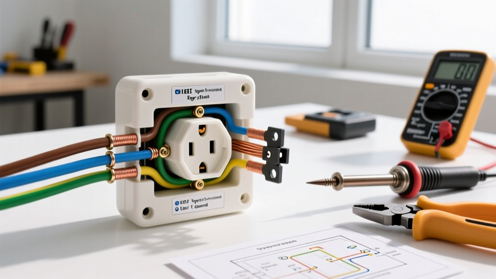
The NEMA 14-50R configuration features four distinct terminals. Understanding the exact pinout is critical, as reversing the neutral and ground, or misidentifying the hot legs, can result in severe shock hazards or destroyed RV appliances.
NEMA 14-50R Pinout and Wire Color Coding
| Terminal Marking | Function | Standard Wire Color (Copper) | Voltage Potential | Physical Pin Shape |
|---|---|---|---|---|
| X | Hot Leg 1 | Black | 120V to Neutral / 240V to Y | Angled Flat Blade |
| Y | Hot Leg 2 | Red | 120V to Neutral / 240V to X | Angled Flat Blade |
| W | Neutral | White | 0V (Current Carrying) | Straight Flat Blade |
| G | Equipment Ground | Bare Copper or Green | 0V (Safety Path) | Round Pin (U-Shape) |
When looking at the face of the NEMA 14-50R receptacle with the ground pin at the bottom (the standard orientation), the Neutral (W) is on the left, Hot X is on the top right, and Hot Y is on the bottom right. Always verify your specific receptacle manufacturer's stamping, as some industrial models label terminals slightly differently on the rear housing.
Wire Sizing, Conduit, and Voltage Drop Calculations
A 50-amp breaker requires wire capable of safely carrying 50 amps without exceeding its thermal rating. However, RV loads are often considered continuous (running for 3 hours or more), meaning voltage drop over distance becomes a critical safety factor. According to the RV Industry Association (RVIA), low voltage at the pedestal can cause RV air conditioner compressors to overheat and fail.
Minimum Wire Sizing by Material
- Copper: 6 AWG THHN/THWN-2 (Rated for 75°C/90°C terminations).
- Aluminum: 4 AWG XHHW-2 (Aluminum requires upsizing due to higher resistance and thermal expansion characteristics).
Voltage Drop Chart (50A Load at 240V/120V Split-Phase)
NEC recommends keeping voltage drop under 3% for branch circuits. If your pedestal is far from the main panel, you must upsize your wire.
| Distance from Panel | 6 AWG Copper Drop % | 4 AWG Aluminum Drop % | Required Action |
|---|---|---|---|
| 50 Feet | 1.5% | 2.1% | Acceptable (Standard 6 AWG Cu / 4 AWG Al) |
| 100 Feet | 3.0% | 4.2% | Upsize Aluminum to 2 AWG; Copper is borderline |
| 150 Feet | 4.5% | 6.3% | Upsize Copper to 4 AWG; Aluminum to 1/0 AWG |
Hardware Selection: Avoiding Thermal Failure Modes
This is where most DIY installations fail catastrophically. Standard residential-grade NEMA 14-50R receptacles (often priced around $12 to $15) are designed for intermittent loads, such as an electric oven that cycles on and off. They are not designed for an RV pulling 45 amps continuously for 8 hours during a summer heatwave.
Under continuous load, the thin internal brass contacts in cheap receptacles heat up, lose their spring tension (a process called annealing), and create a high-resistance connection. This leads to melting, arcing, and fires. For RV applications, you must install an Industrial-Grade receptacle.
Recommended Heavy-Duty Receptacles:
- Hubbell HBL9450A: The gold standard for RV pedestals. Features heavy-duty beryllium copper contacts, glass-reinforced nylon housing, and high clamping force. (Retail: $95 - $115).
- Bryant 9450FR: Bryant is Hubbell's commercial line; this model shares the same internal architecture and is an excellent, slightly more affordable alternative. (Retail: $80 - $95).
For a complete guide on heavy-duty wiring devices, consult the Hubbell Wiring Systems catalog for specific torque and strip-length specifications.
Step-by-Step Installation & Torque Requirements
Follow this precise sequence to ensure a code-compliant and mechanically sound termination.
- Strip the Wire: Strip exactly 5/8-inch of insulation from the 6 AWG conductors. Do not nick the copper strands, as this creates a weak point prone to snapping under thermal expansion.
- Land the Ground First: Terminate the bare/green wire to the 'G' terminal. This ensures the chassis is grounded before any live conductors are connected.
- Land the Neutral: Terminate the white wire to the 'W' terminal. Ensure no bare copper is exposed outside the terminal barrel.
- Land the Hot Legs: Terminate Black to 'X' and Red to 'Y'. The phase rotation (which hot is X or Y) does not matter for standard RV appliances, as they utilize 120V from either leg to neutral.
- Apply Calibrated Torque: Using a calibrated torque screwdriver (e.g., CDI Torque or Wera), tighten all four terminal screws to exactly 22 inch-pounds (verify against your specific receptacle's spec sheet). This satisfies NEC 110.14(D).
- Secure the Receptacle: Mount the receptacle to the weatherproof box using the provided corrosion-resistant screws. Ensure the in-use weather cover closes completely over the plugged-in RV cord.
Common Code Violations and Failure Modes
When inspecting RV pedestals, electrical inspectors frequently encounter the same dangerous errors. Avoid these at all costs:
- The 'Dryer Cord' Adaptation: Using a NEMA 14-30 (30-amp dryer) receptacle and attempting to adapt it to a 50-amp RV plug. This will overload the 30-amp wire and cause a fire before the breaker trips.
- Neutral-to-Ground Bonding at the Pedestal: If you install a bonding screw or jumper in the RV pedestal, neutral return current will travel along the RV's grounding wire and metal chassis. This creates a severe shock hazard for anyone touching the RV while standing on damp earth.
- Backstabbing or Using Undersized Lugs: 6 AWG wire is too thick for standard screw-terminal loops on cheap receptacles. Always use the deep barrel terminals found on industrial 14-50R models.
- Ignoring In-Use Covers: NEC 406.9 requires all outdoor 15- and 20-amp receptacles to have in-use covers. While 50-amp RV pedestals are governed by Article 551, best practice and local AHJ (Authority Having Jurisdiction) interpretations almost universally mandate a weatherproof, in-use cover to prevent water intrusion into the high-amperage terminals.
Frequently Asked Questions (FAQ)
Does a 50-amp RV outlet require a GFCI breaker?
The 2023 and upcoming 2026 NEC cycles have expanded GFCI requirements for outdoor receptacles (NEC 210.8(F)). However, dedicated RV park supply equipment (pedestals) governed by Article 551 often has specific exemptions or requires specialized ground-fault protection of equipment (GFPE) rather than standard 5mA personnel GFCI breakers, which can nuisance-trip when large RV inverters and chargers are connected. Always consult your local AHJ for the exact interpretation in your municipality.
Can I wire a 50-amp RV plug to a single-pole 50-amp breaker?
No. A NEMA 14-50R requires a 2-pole, 50-amp breaker to supply both 120V legs (X and Y) that are 180 degrees out of phase. Wiring both hot terminals to the same single phase will result in 0 volts across 240V appliances and will overload the shared neutral wire, causing it to melt.
Why is my RV's EMS (Electrical Management System) showing an open ground?
If your RV's built-in EMS throws an 'Open Ground' error, the issue is almost always a disconnected or poorly torqued ground wire at the pedestal's 'G' terminal, or a broken ground pin on the RV's male plug. Do not bypass the EMS to force power; trace the ground fault immediately.