
Understanding the US Standard Electrical Outlet
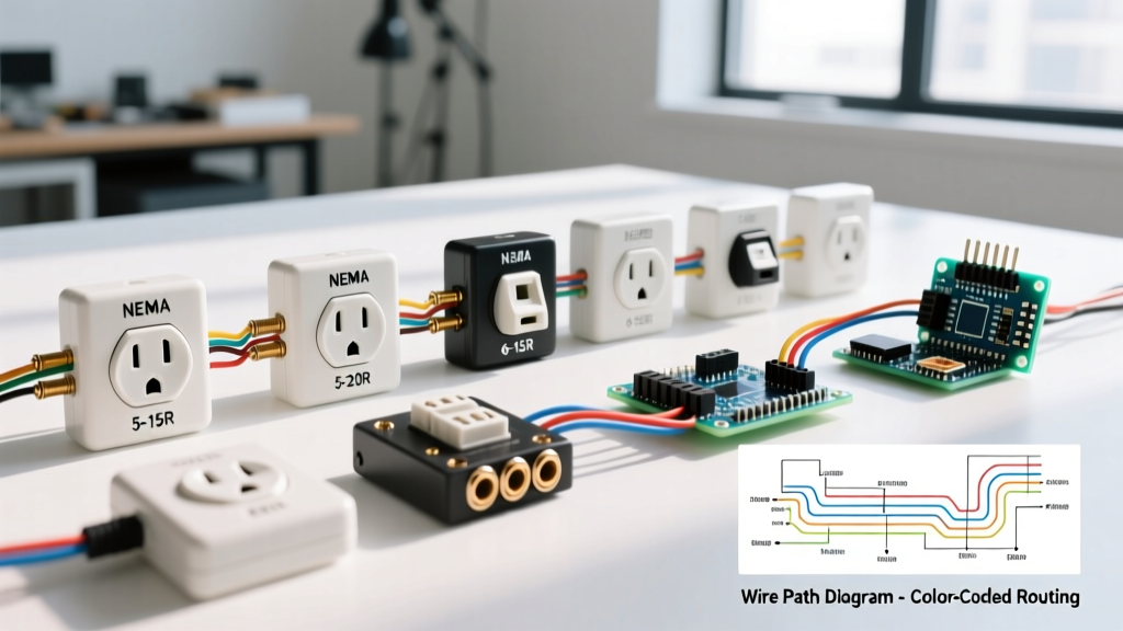
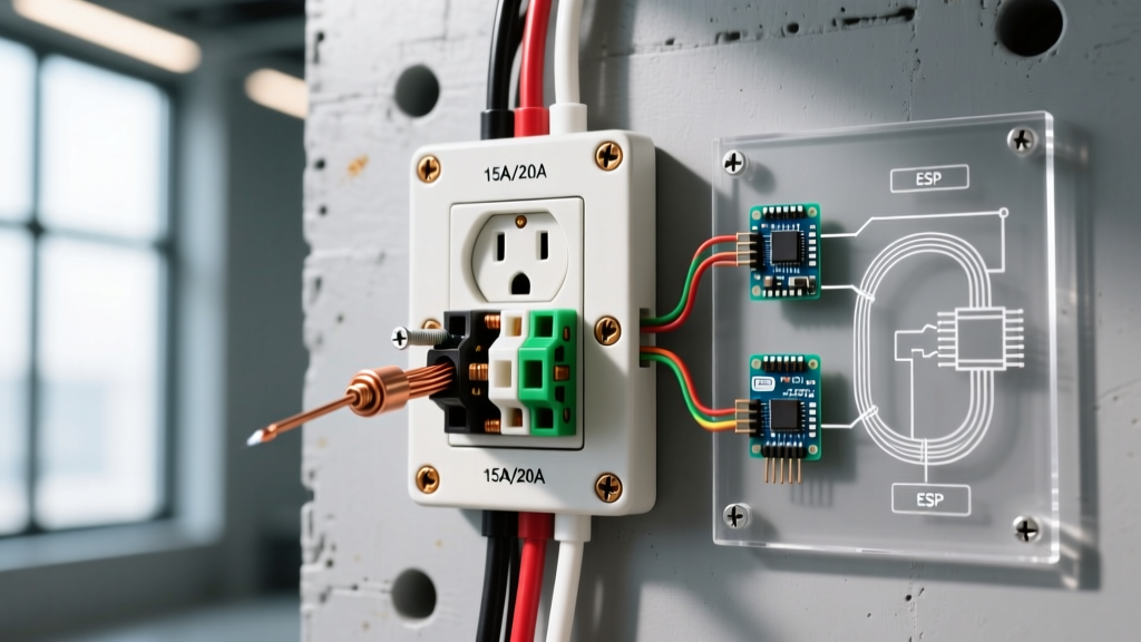
When electricians and DIYers refer to a US standard electrical outlet, they are technically referencing the NEMA 5-15R (15-amp) or NEMA 5-20R (20-amp) 125-volt receptacle. These devices are the backbone of North American residential and commercial power distribution. As of 2026, the baseline requirements for these receptacles have evolved significantly from the basic designs of the 20th century. Modern installations demand strict adherence to the National Electrical Code (NEC), particularly regarding Tamper-Resistant Receptacles (TRR) and precise terminal torque specifications.
According to the Electrical Safety Foundation International (ESFI), tamper-resistant receptacles are now mandatory in almost all residential living spaces, a code requirement designed to prevent childhood electrical shocks by utilizing internal shutter mechanisms. Furthermore, the National Electrical Code (NEC) has introduced stringent rules regarding wire termination torque to prevent arc faults caused by loose connections over time.
This comprehensive, step-by-step guide will walk you through the professional installation of a standard US electrical outlet, focusing on best practices, code compliance, and long-term reliability.
NEMA 5-15R vs. NEMA 5-20R: Which Do You Need?
Before stripping any wires, you must verify the circuit's amperage and wire gauge. Installing a 20-amp receptacle on a 15-amp circuit is a code violation, and installing a 15-amp receptacle on a 20-amp circuit can create a fire hazard if a single plug draws the full 20 amps.
| Feature | NEMA 5-15R (Standard 15A) | NEMA 5-20R (Standard 20A) |
|---|---|---|
| Max Amperage | 15 Amps | 20 Amps |
| Required Wire Gauge | 14 AWG (or 12 AWG) | 12 AWG (or 10 AWG) |
| Breaker Size | 15A | 20A |
| Slot Configuration | Two parallel vertical slots | One vertical, one horizontal (T-slot) |
| Average 2026 Cost | $2.50 - $4.00 (TR models) | $3.50 - $6.50 (TR models) |
| Common Applications | Bedrooms, living rooms, hallways | Kitchens, garages, bathrooms, workshops |
Essential Tools and Materials for 2026
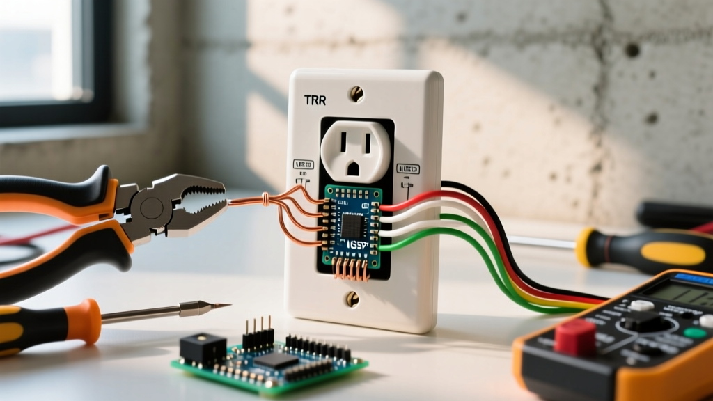
Professional results require professional tools. While a basic screwdriver might get the job done, modern NEC compliance requires calibrated precision.
- Receptacle: Leviton Decora 5320-WMP (15A TR) or Hubbell 5262 (20A TR).
- Wire Strippers: Klein Tools 11063 (for 14/12 AWG solid copper).
- Torque Screwdriver: Wiha 645P or Klein Tools 70650 (Calibrated, adjustable up to 40 in-lbs).
- Voltage Tester: Fluke 117 True-RMS Multimeter and Fluke NCVT-3 Non-Contact Voltage Tester.
- Receptacle Tester: Gardner Bender GRT-101 or Amprobe IN-101.
- Connectors: Wago 221 Lever-Nuts (for pigtailing) or Ideal 33-090 WireNuts.
Step-by-Step Installation Guide
Step 1: Power Verification and Lockout
Never assume a circuit is dead based on the wall switch or a tripped breaker label. Turn off the breaker at the main panel. Use a Non-Contact Voltage Tester (NCVT) to scan the outlet face, then remove the cover plate. Test across the hot (black) and neutral (white) wires, and hot to ground (bare/green), using a multimeter. The reading must be exactly 0.0V. For maximum safety, apply a lockout/tagout device to the breaker panel to prevent accidental re-energization while you work.
Step 2: Box Preparation and Wire Stripping
Clean the electrical box of drywall dust and debris, which can trap heat or interfere with the seating of the receptacle. Inspect the existing wires for nicked insulation or heat damage; if the insulation is brittle or cracked, trim it back to fresh wire using wire strippers.
Strip Length: Use the built-in gauge on the back of your new receptacle. For most modern 15A and 20A TR receptacles, the strip length is exactly 3/4 inch. Stripping too little leaves exposed copper outside the terminal (a shock hazard), while stripping too much prevents the wire from seating fully in the terminal well.
Step 3: Pigtailing (The Professional Standard)
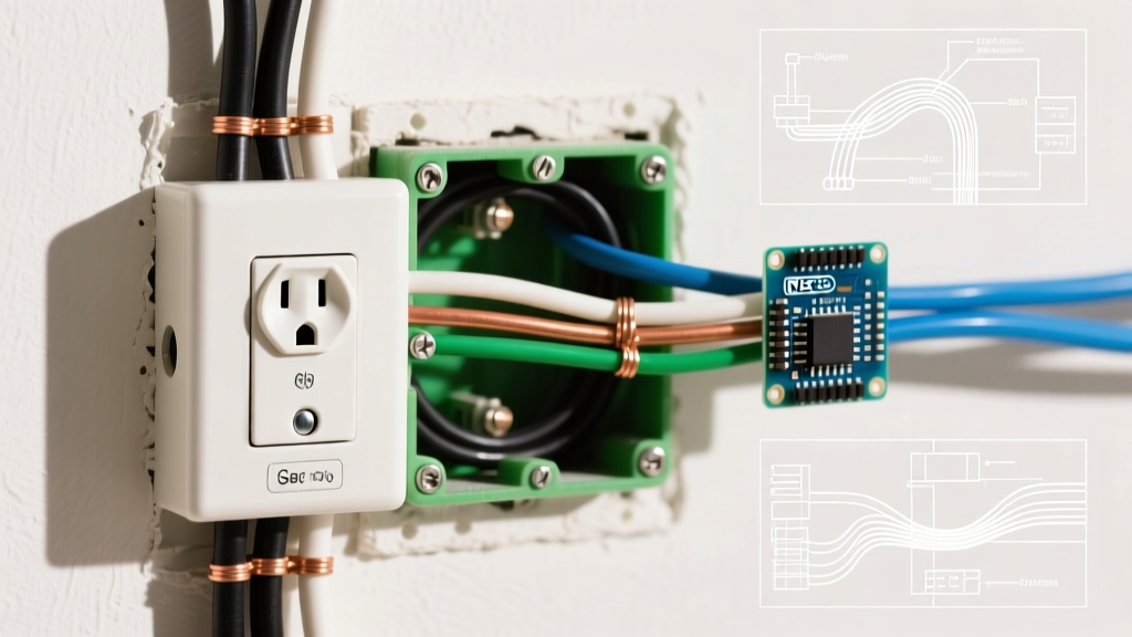
If this outlet is in the middle of a circuit (meaning there are two sets of black, white, and ground wires entering the box), you must use pigtails. Do not use the receptacle's internal bus bars to pass current to downstream devices. If the receptacle fails or is removed, the downstream devices and the grounding path will be broken—a direct violation of NEC safety principles.
- Connect the two incoming black wires and a 6-inch black pigtail using a Wago 221 lever-nut.
- Repeat for the white neutral wires.
- Connect all bare/green ground wires and a ground pigtail together. Note: In metal boxes, the box itself must also be grounded via a grounding screw.
Step 4: Wire Termination and the "Clockwise Rule"
When connecting the pigtails to the receptacle, always use the side-screw terminals or the screw-clamp back-wiring plates. Never use the push-in "backstab" terminals. Push-in terminals rely on a small spring-metal wedge that grips the wire. Under heavy electrical loads, thermal cycling (heating and cooling) causes the wire and terminal to expand and contract. Over years, this loosens the push-in grip, leading to high-resistance connections, arcing, and potentially electrical fires.
Form a "J-hook" in the stripped end of your wire using needle-nose pliers. Hook the wire around the terminal screw in a clockwise direction. This ensures that as you tighten the screw (which turns clockwise), the loop is pulled tighter around the screw shaft rather than pushed outward.
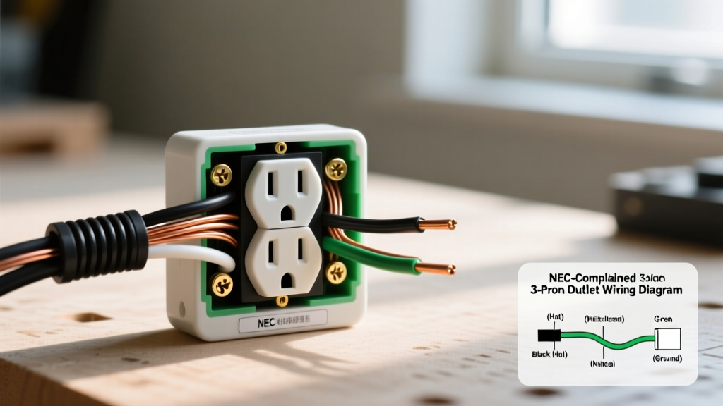
- Brass Screws: Hot/Line (Black wire)
- Silver Screws: Neutral (White wire)
- Green Screw: Equipment Ground (Bare/Green wire)
Step 5: Applying Precise Torque (NEC 110.14(D))
Since the 2017 NEC update, and strictly enforced in 2026 inspections, electrical safety guidelines and NEC 110.14(D) require that terminal connections be tightened to the manufacturer's specified torque using a calibrated torque screwdriver.
Check the back of your receptacle. Most standard Leviton and Hubbell 15A/20A receptacles specify 14 in-lbs (inch-pounds) for side-wire terminals. Set your torque screwdriver to 14 in-lbs and tighten each screw until the driver clicks. This eliminates human error, preventing both under-tightening (which causes arcing) and over-tightening (which strips the brass threads or shears the wire).
Step 6: Seating, Mounting, and Testing
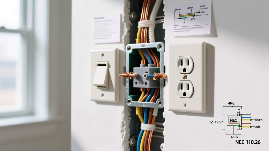
Carefully fold the wires into the back of the box. Push the wires back, not the receptacle, to avoid pinching the copper against the metal box edges. Mount the receptacle using the provided 6-32 machine screws. Use a torpedo level to ensure the strap is perfectly plumb before fully tightening.
Restore power at the breaker. Insert a receptacle tester (like the Gardner Bender GRT-101). You are looking for two solid yellow lights, indicating "Correct" wiring. If you see a red light or a single yellow light, you have reverse polarity, an open ground, or a hot/neutral swap. Turn the power back off and re-verify your terminations.
Common Failure Modes and Edge Cases
Pro-Tip: Multi-Wire Branch Circuits (MWBC)
If you open a box and find a black wire, a red wire, and a white wire sharing a single neutral, you are dealing with an MWBC. The NEC strictly requires that the breakers feeding an MWBC be equipped with a handle tie or a double-pole breaker. If you break the shared neutral while the circuit is energized, you will create a series circuit that sends 240V through your 120V appliances, instantly destroying them and creating a severe fire hazard.
1. The "Backstab" Meltdown
As mentioned, push-in terminals are the leading cause of receptacle degradation in older homes. If you are replacing an old outlet and notice the plastic casing around the backstab terminals is brown or melted, this is a sign of a high-resistance thermal event. Cut the damaged wire back to bright, clean copper before terminating the new device.
2. Drywall Pinching and Strap Bending
If the drywall was cut too close to the electrical box, the receptacle strap may bend when you tighten the mounting screws. This puts mechanical stress on the internal TRR shutters, causing plugs to bind or fail to insert. Use plastic outlet shims (caterpillars) behind the strap ears to bridge the gap between the box and the drywall, ensuring the receptacle sits perfectly flush without bending.
3. Weather-Resistant (WR) Requirements
If you are installing a US standard electrical outlet outdoors, in a garage, or in a damp location, standard TR receptacles are not enough. NEC 406.9 requires Weather-Resistant (WR) receptacles. These feature UV-resistant face materials and nickel-plated brass terminal screws to prevent corrosion from humidity and temperature swings. Look for the "WR" stamp on the strap of the device.
Frequently Asked Questions
Can I install a 20-amp outlet on a 15-amp breaker?
No. While a 20-amp receptacle (NEMA 5-20R) is physically capable of handling 15 amps, the NEC prohibits installing a receptacle with a higher ampere rating than the circuit breaker protecting it. The breaker must match or exceed the receptacle rating, but a 15A circuit must exclusively use 15A receptacles.
Why is it so hard to push a plug into my new outlet?
This is the Tamper-Resistant (TR) shutter system working as intended. The internal shutters require equal, simultaneous pressure on both the hot and neutral prongs to open. If you push a plug in at an angle, or if the prongs are bent, the shutters will lock. Ensure your plug prongs are straight and push firmly and evenly.
Do I need to wrap electrical tape around the terminal screws?
Wrapping black electrical tape around the sides of the receptacle to cover the terminal screws is an outdated practice from the mid-20th century. Modern electrical boxes are sized to provide adequate clearance, and the NEC does not require tape. In fact, tape can trap heat and degrade into a sticky residue over time. Rely on proper box sizing and correct wire termination instead.